
Software based brake shoe wear determination

a software and shoe technology, applied in the direction of braking systems, shock absorbers, instruments, etc., can solve the problems of unreliability of spot inspection, heightened risk of equipment damage, and difficulty in using simple distance or time-based intervals to inspect the wear of friction brake materials, so as to reduce the amount of friction brake effort and reduce the wear rate of the shoe/pad material

Inactive Publication Date: 2004-07-15
WESTINGHOUSE AIR BRAKE TECH CORP
View PDF1 Cites 17 Cited by
  • Summary
  • Abstract
  • Description
  • Claims
  • Application Information

AI Technical Summary

Benefits of technology

[0006] Another object of the present invention is to provide a software-based brake shoe / pad wear determination apparatus which will provide maintenance personnel with an indication of wear to reduce equipment damage due to using the brake shoes or brake pads beyond their useful life.
[0008] Another object of the present invention is to provide software-based brake shoe / pad wear determination apparatus which enables measuring the friction brake effort in terms of pressure.
[0012] Another object of the present invention is to provide a software-based brake shoe / pad wear determination apparatus wherein the brake system may be electronically configured to reduce the amount of friction brake effort supplied, reducing the wear rate of the shoe / pad material.

Problems solved by technology

As a result, it is difficult to use simple distance or time based intervals to inspect the friction brake material for wear.
If there is a failure in the dynamic friction brake equipment and this failure goes unreported there is a heightened risk for equipment damage due to uneven friction brake usage between different parts of the same train consists.
Therefore, making spot inspections unreliable.
In the prior art, if the brake system equipment failure were to occur just after a scheduled train inspection, there is the potential to completely wear the brake shoe / pad away before the next scheduled inspection due to continual changes in dynamic and friction braking effort.

Method used


Image

  • Software based brake shoe wear determination
  • Software based brake shoe wear determination

Examples


Embodiment Construction

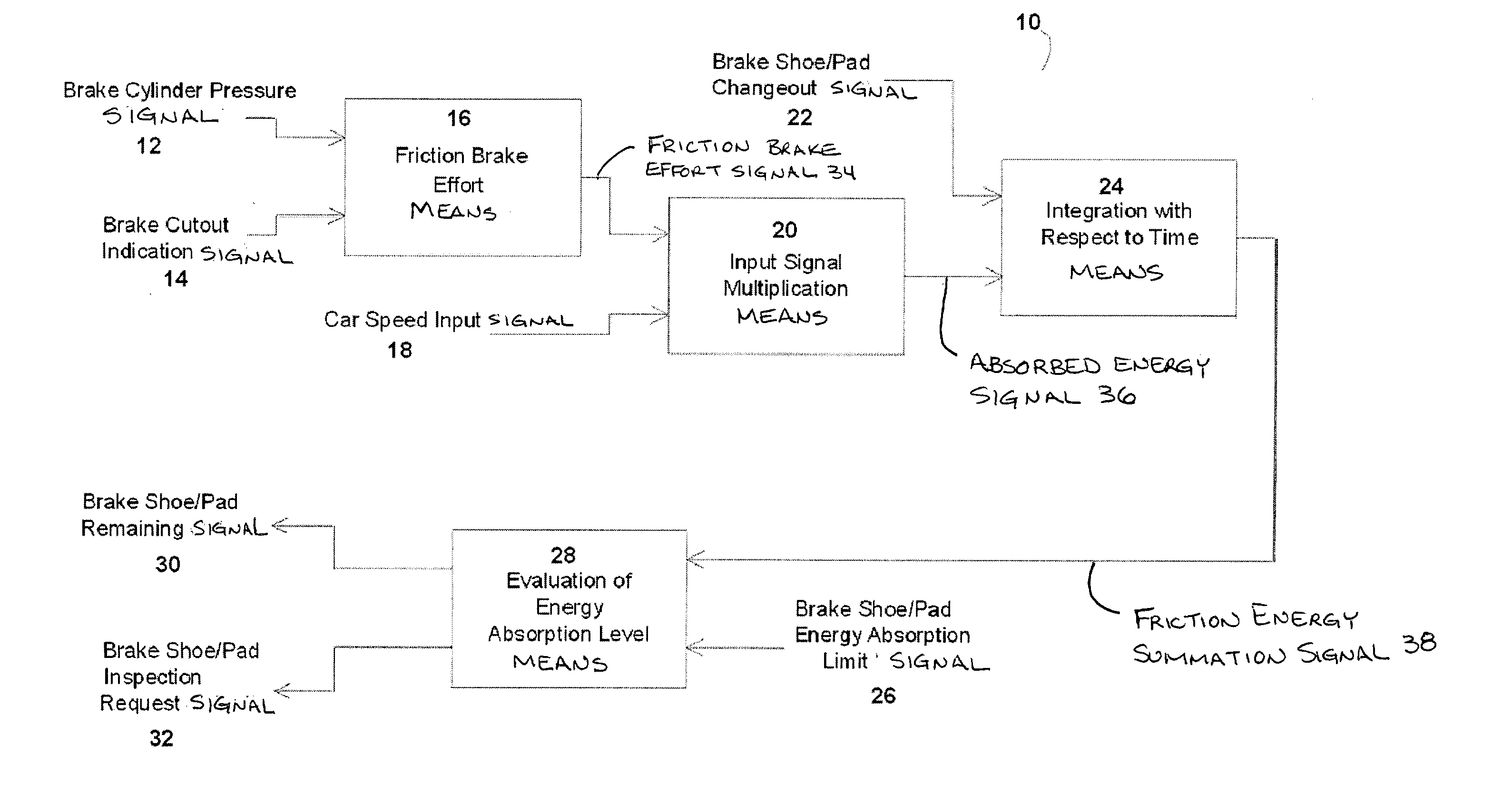
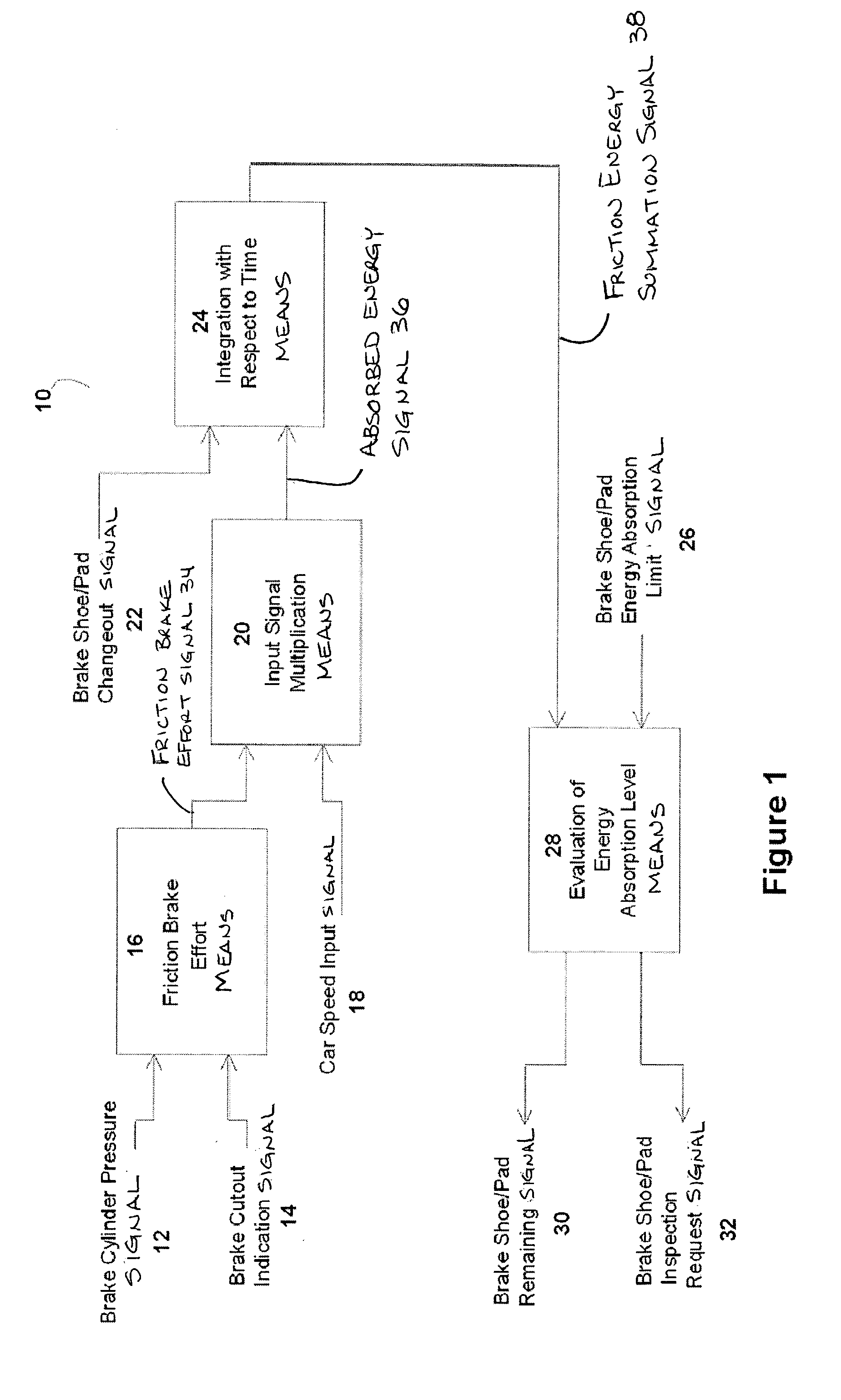
[0017] In the presently preferred embodiment, this invention provides an apparatus to annunciate electronically through a software-based brake shoe / pad wear determination program, when brake material should be inspected and / or replaced based on the amount of energy supplied over time. The presently preferred embodiment of this invention also provides an apparatus to annunciate electronically to maintenance personnel and operators, through this software-based brake shoe wear determination program, remaining brake shoe / pad thickness in descending percentages related to replacement, wear limit and equipment damage, thus avoiding equipment damage as a result of undetected rapid wear of the brake shoe / pad.

[0018] In the presently preferred embodiment, there is provided a software-based program for monitoring transit vehicle brake shoe / pad wear for inspecting and replacing brake shoes / pads before damage to equipment occurs.

[0019] Reference is now made to FIG. 1. Illustrated therein is a pr...


PUM


Abstract

By calculating the energy used by the friction brake equipment, the amount of friction brake shoe / pad wear can be monitored. As the amount of energy supplied reaches a percentage of the friction brake shoe / pad energy design limit, an indication for inspection is provided. If the supplied friction energy continues to increase beyond this point, the brake material must be replaced. The software logic limits are tunable for custom configuring by the transit authority and maintenance personnel. This invention measures the amount of friction effort supplied with respect to time and distance in a software controlled brake system. Furthermore, this invention allows the software to determine when the friction brake material must be replaced based on actual data, which simplifies the maintenance personnel operation procedures, maximizes brake material wear, and avoids costly damage from braking with worn out shoes / pads. The material life remaining for friction brakes is determined currently by a visual inspection followed by a 'best guess' as to whether the material will last until the next scheduled inspection. This invention will annunciate through the software logic program when the friction material requires inspection and replacement. Additionally, the invention provides software logic to indicate the remaining material thickness.

Description

[0001] The present invention generally relates, to brake shoes and pads used on a transit railway vehicle and, more particularly, this invention relates to a computer software program for indicating and controlling brake shoe and / or brake pad wear on an electronically controlled passenger transit vehicle and, still more particularly, this invention relates to a software program in a microprocessor system designed to monitor continuous brake shoe / pad thickness in percentages and display wear data to maintenance personnel and operators between scheduled inspection intervals.[0002] The following background information is provided to assist the reader to understand the invention described and claimed herein. Accordingly, any terms used herein are not intended to be limited to any particular narrow interpretation unless specifically so indicated.[0003] There is presently known in the prior art, typically on transit vehicles utilizing electronic controls, that electrically propelled trans...

Claims


Application Information

Patent Timeline
IPC IPC(8): B60K6/20F16D66/00B60T17/18B60T17/22G06F7/00G06F19/00
CPCB60T17/228F16D66/02Y10T477/80Y10T477/83F16D2066/006
Inventor DEWBERRY, JAMES T.SCHWEIKERT, DAVID E.SCHARPF, ROBERT N.
Owner WESTINGHOUSE AIR BRAKE TECH CORP
Learn More