Device for joining flat, thin members that rest against another

a technology of thin members and flat joints, applied in the direction of rod connections, mechanical devices, walls, etc., can solve the problems of substantial force on the steps, inability to use the members, and little material available for clamping the additional snap-fi

Inactive Publication Date:
View PDF10 Cites 124 Cited by
  • Summary
  • Abstract
  • Description
  • Claims
  • Application Information

AI Technical Summary

Benefits of technology

0009] According to the invention, this objective is achieved by virtue of the joining element having, on its part that can be inserted in the manner of an external tongue in the longitudinal center on its side that faces away from the visible surface of the members, one continuous web or a plurality of aligned webs that preferably protrude at a right angle, from which detent webs protrude on both sides, each of which has a detent projection that projects toward the external-tongue-like part, and on the underside of the member, which faces away from its visible surface, detent grooves being provided that run parallel to the adjacent edge at a distance corresponding to the width of the detent webs. In this way the joining elements that are integrally molded with the members, or molded in them, are not subjected to bending stress, but only to compression, because bending only occurs on the joining element, and specifically between the part that can be inserted in the manner of an external tongue and the associated detent webs, whereas the projecting area of the member that is to be inserted between these two parts of the joining element is subject to no bending forces whatsoever, because the groove walls, which have the part that can be inserted in the manner of an external tongue, run parallel to each other, and bending of the groove cheeks of the members is thus avoided.

Problems solved by technology

These known configurations have the disadvantage that, when installing them, there must be two gluing operations at each plate abutment because the external tongue has to be anchored with both longitudinal edges, namely once on a plate-like member and with the other longitudinal edge in the other member.
In members formed from fiber plates, deficient quality in the fiber plates can in fact cause the groove walls to break through or break away, causing this member to then be unusable.
A design of this type has the disadvantage, especially with thin plates, that only a little material is available for clamping the additional snap-fit organ, whereby the step flanks must absorb the forces that are required to move away the snap-fit element when joining together the plates.
Although it is described within the context of this design that the member to be joined is swung "tongue-first" into the "groove" on the other member, this requires an appropriate amount of play between the step walls that run roughly parallel to the top surface, because otherwise the swinging in is not possible or is possible only when swinging away the snap-fit organ, which again exerts substantial forces on the steps.
However, such play permits limited movement on both sides, which is especially disadvantageous for floors.
Designs of this type are not usable in terms of manufacturing technology with members that are based on wood materials, because in the process wall thicknesses that are too thin may result, which may easily lead to a danger of breakage when joining and also when shipment is not entirely proper.

Method used


Image

  • Device for joining flat, thin members that rest against another
  • Device for joining flat, thin members that rest against another

Examples


Embodiment Construction

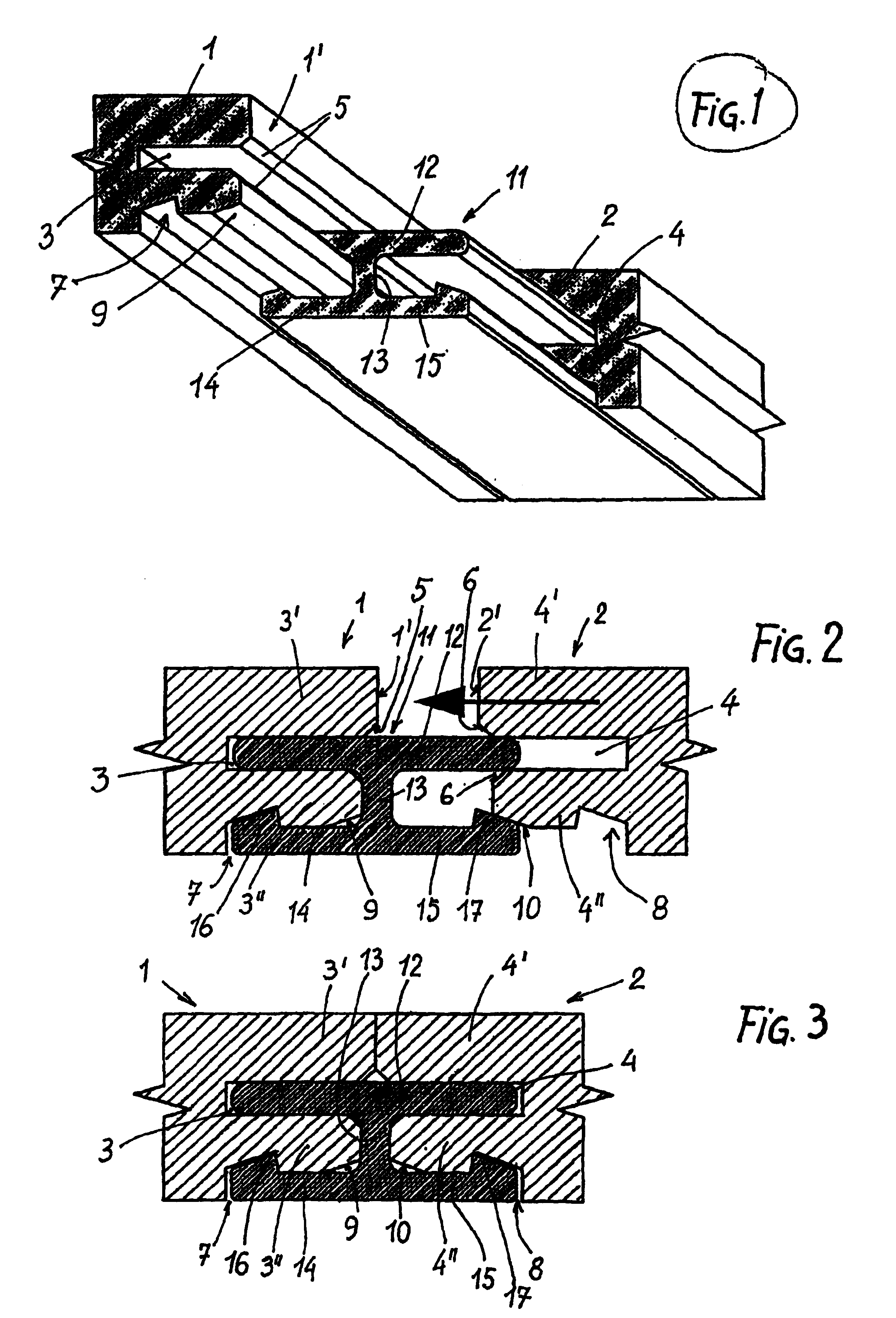
[0016] The two members are labeled 1 and 2 that are to be joined side-by-side along their narrow faces 1', 2'. Members 1, 2 on their narrow faces 1', 2' have grooves 3, 4 whose lateral flanks run parallel to each other. In the given exemplary embodiment, the lateral surfaces of grooves 3, 4 also run parallel to the top of members 1, 2. The lateral walls of grooves 3, 4 transition into narrow faces 1', 2' via bevels 5 or 6. On the bottom, members 1, 2 have detent grooves 7, 8 that are provided with run-in surfaces 9, 10, which are disposed running outward from narrow faces 1', 2' at an angle to the bottom of members 1, 2 and transition into detent grooves 7, 8.

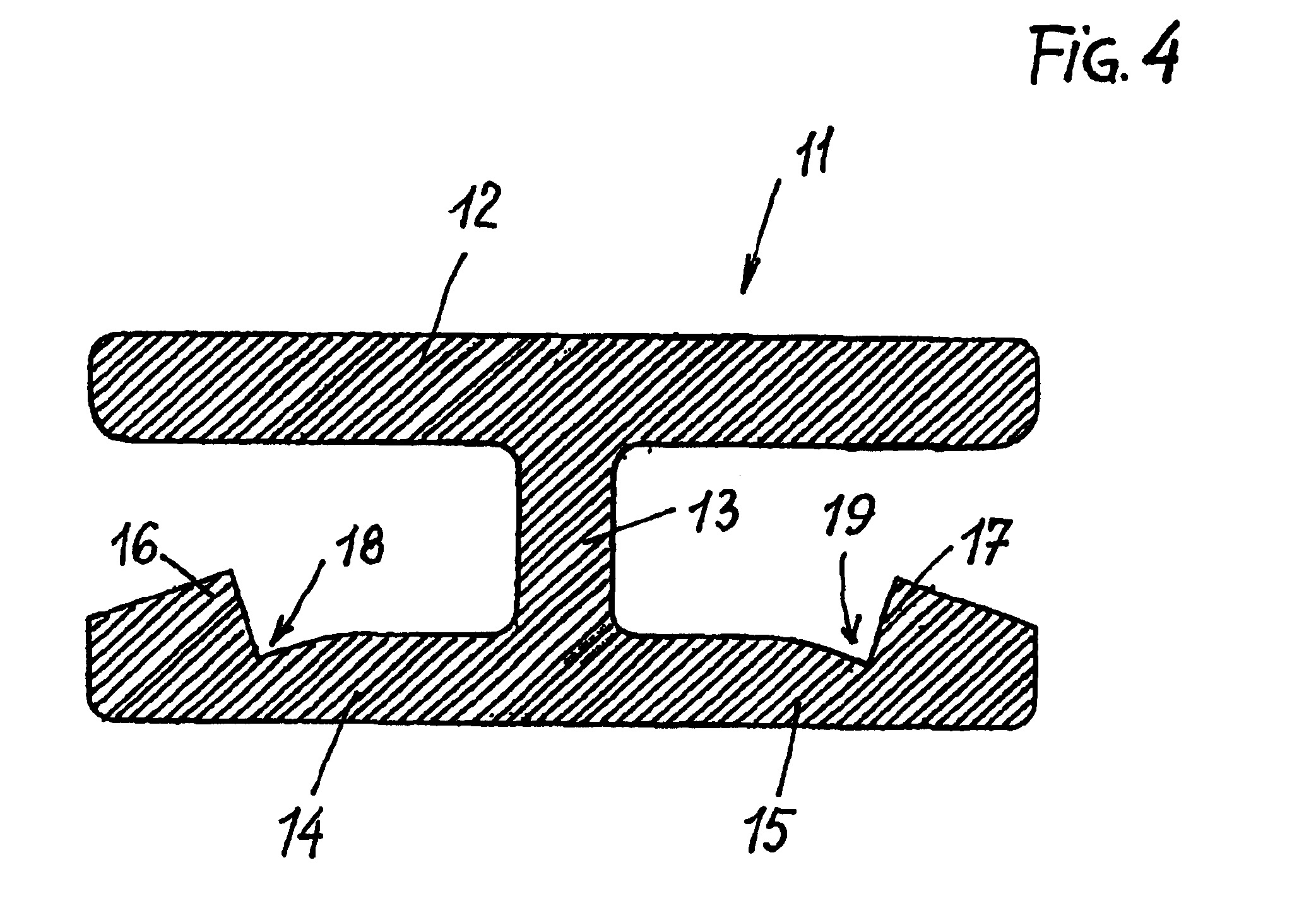
[0017] A joining element 11, which has an external-tongue-like part 12 that can be inserted into grooves 3, 4 in such a manner as to bridge the inner gap, is provided for joining members 1, 2. The open longitudinal edges of tongue-like part 12 are, as can be seen in the figures, rounded or beveled in order to more easily be int...


PUM


Abstract

The system relates to a system for joining flat, relatively thin members that adjoin one another along their narrow face, the members having grooves incorporated into the narrow faces that are parallel to the surface and have groove walls that are parallel to each other, and the joining element being inserted into the grooves of two adjacent members and bridging the partition gap between the members in the manner of an external tongue. In this context the joining element (11) has, on its part (12) that can be inserted in the manner of an external tongue in the longitudinal center on its side that faces away from the visible surface of the members, one continuous web or a plurality of aligned webs (13) that preferably protrude at a right angle, from which detent webs (14, 15) protrude on both sides, each of which has a detent projection (16, 17) that projects toward the external-tongue-like part (12), and on the bottom of the member (1, 2), which faces away from its visible surface, detent grooves (7, 8) being provided that run parallel to the adjacent edge at a distance corresponding to the width of the detent webs (14, 15).

Description

[0001] 1. Field of the Invention[0002] The invention relates to a system for joining flat, relatively thin members that adjoin one another along their narrow face, the members having grooves incorporated into the narrow faces that are parallel to the surface and have groove walls that are parallel to each other, and the joining element being inserted into the grooves of two adjacent members and bridging the partition gap between the members in the manner of an external tongue.[0003] 2. Background Description[0004] Configurations of this kind have the advantage that all members are formed completely the same; that is, it is not necessary to ensure that a side with a groove always faces a side with a tongue, such members also being substantially easier to manufacture. In the installation of this known configuration, external tongues are used, whereby the flat member to be attached may be attached without regard to its edge configuration. These known configurations have the disadvantag...

Claims


Application Information

Patent Timeline
Patent Type & Authority Applications(United States)
IPC IPC(8): E04B1/684E04F15/02E04F15/04
CPCE04F15/02E04F15/04Y10T403/551E04F2201/0517E04F2201/0115
Inventor KNAUSEDER, FRANZ
Why Eureka
Try Eureka