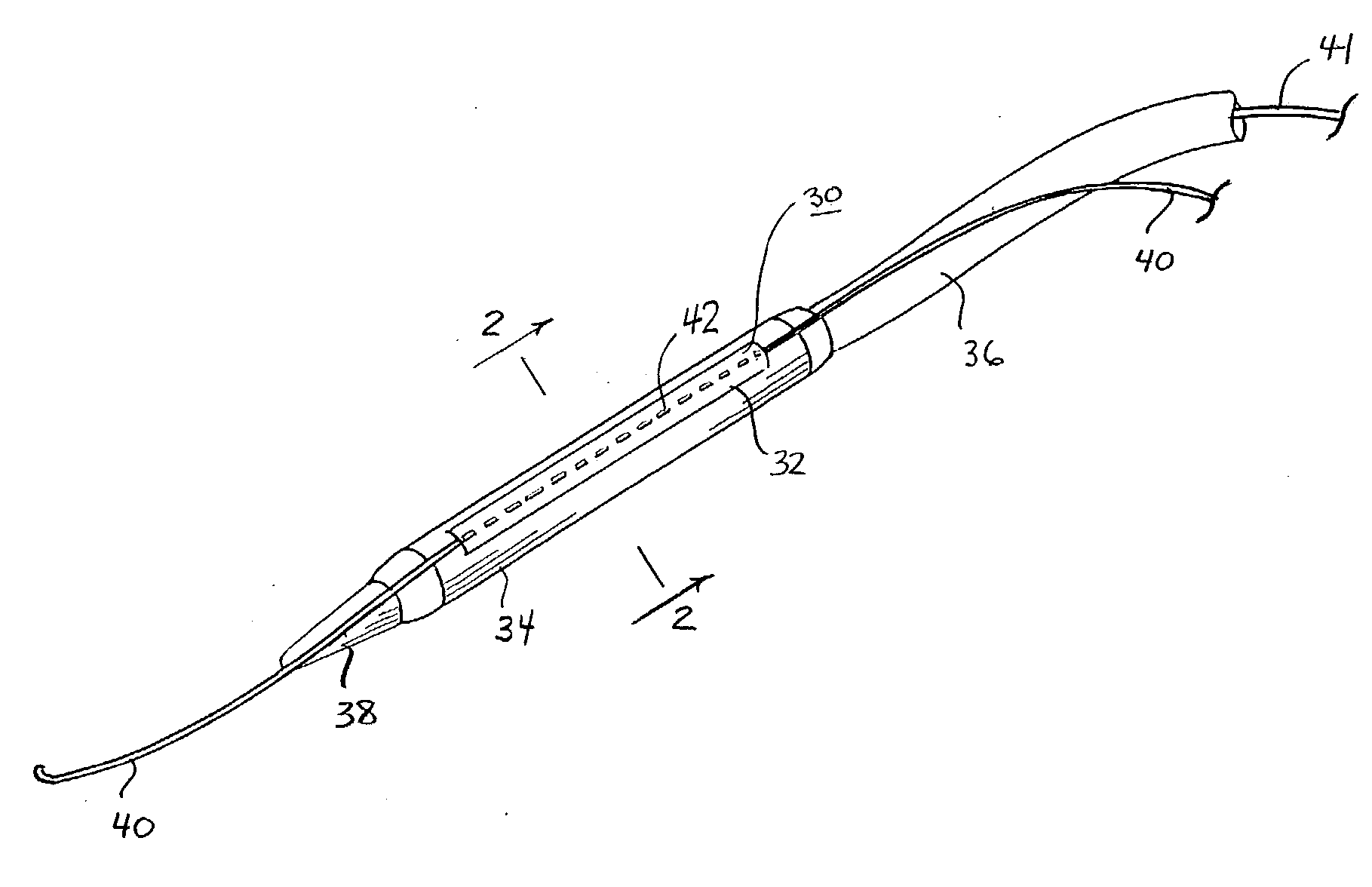
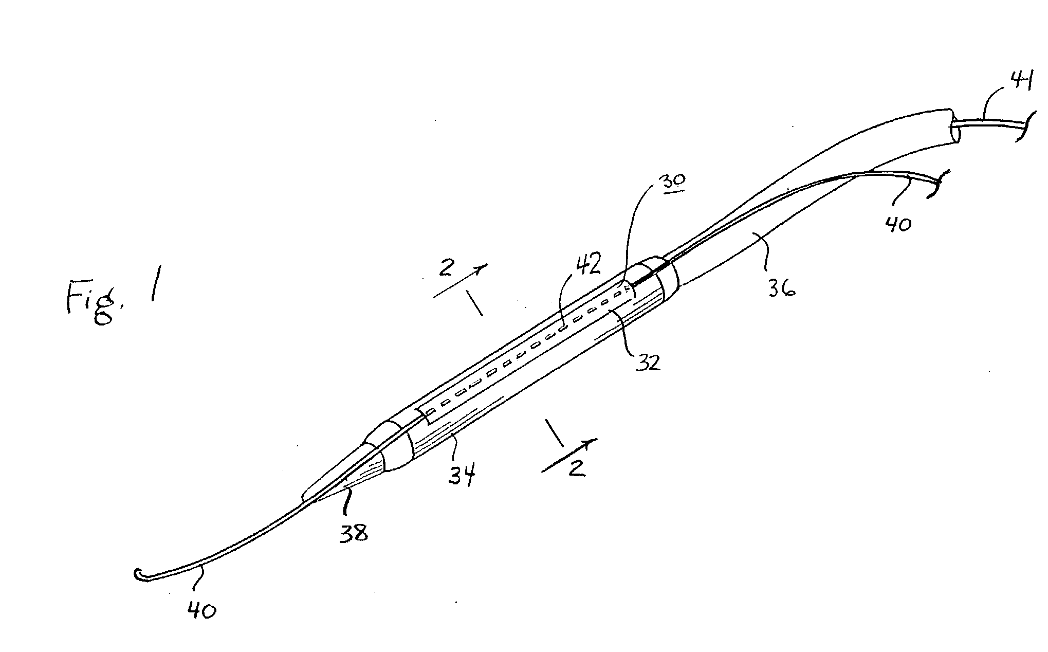
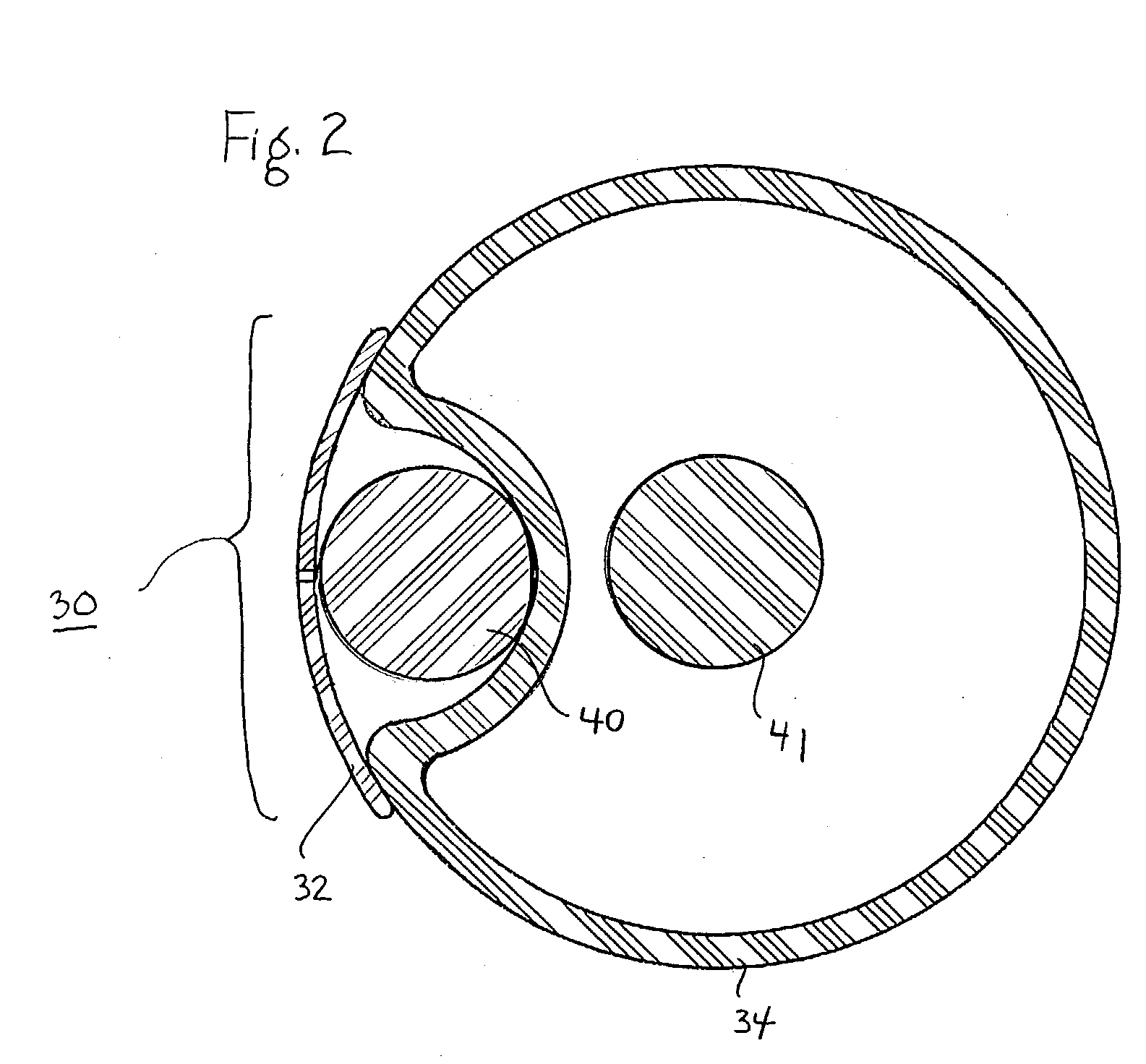
Catheter with disruptable guidewire channel

a technology of guidewire and catheter, which is applied in the field of catheter systems, can solve the problems of limiting the speed with which procedures can be completed and the types of procedures that can be easily performed, and the trackability may be a far greater problem

Inactive Publication Date: 2004-07-22
WL GORE & ASSOC INC
View PDF20 Cites 134 Cited by
  • Summary
  • Abstract
  • Description
  • Claims
  • Application Information

AI Technical Summary

Problems solved by technology

Further, the threading of the entire length of the catheter along the guidewire can be somewhat difficult and time consuming.
Moreover, limiting the speed with which procedures can be completed and the types of procedures that can be easily performed, these techniques require each treatment device to be completely retracted along the guidewire before a further treatment device can be advanced along the same guidewire to the treatment site.
However, in practice these techniques also require each treatment device to be completely retracted along the guidewire before a further treatment implement can be advanced along the guidewire to the treatment site.
While these devices may deliver some of the same benefits of the conventional rapid exchange catheters, trackability may be a far greater problem since the guidewire is attached to the treatment catheter only at the very tip of the catheter.
Additionally, depending upon the dimensions and stiffness of the tube housing the guidewire lumen (or, in the case of the Solar et al. device, of the "advancement member"), its presence on the outside of the treatment device may interfere with the proper operation of the treatment device.
Again, the sleeve is disruptable to cause a guidewire placed within the sleeve to free, in whole or in part, from the implement upon disruption of the sleeve.
However, the present inventor has realized that once the treatment implement is correctly positioned within the treatment site and treatment has occurred, there is no reason why the treatment implement must remain on the guidewire for its subsequent removal from the body.
This problem can present itself when fluoroscopy fails to detect the second distal defect prior to treatment of the first defect.

Method used


Image

  • Catheter with disruptable guidewire channel
  • Catheter with disruptable guidewire channel
  • Catheter with disruptable guidewire channel

Examples


Embodiment Construction

[0107] One embodiment of the present invention can be constructed by modifying a commercially available balloon catheter device.

[0108] A 4.0 mm.times.30 mm RX GEMINI Coronary Balloon Dilatation Catheter available from Guidant / ACS of Santa Clara, Calif., may be used as the starting catheter device and is modified in the following manner:

[0109] 1. Insert a 0.36 mm diameter stainless steel wire in the tip and advance it proximally until it exits the RX port.

[0110] 2. Measure the distance from the tip to RX port.

[0111] 3. Remove and cut the 0.36 mm wire to the measured length.

[0112] 4. Reinsert the 0.36 mm wire. Use the EFD dispensing tip to wick Loctite 4014 into the proximal RX channel and at the distal tip to secure the 0.36 mm wire.

[0113] 5. A sleeve of the present invention is cut from a film or tube of expanded PTFE having the following dimensions: not longer than the balloon, but long enough to provide optimal trackability; the width should be at least as wide as the diameter of ...


PUM


Abstract

The present invention is a catheter device that includes a disruptable guidewire channel. The guidewire channel is configured to provide necessary trackability of the catheter along the guidewire during introduction of the catheter to a treatment site. Once treatment is completed, the guidewire channel can then be disrupted so as to free the guidewire from the catheter in situ. The apparatus of the present invention provides distinct advantages over existing over-the-wire and rapid exchange catheter introduction methods, including the ability to achieve much faster treatment implement exchanges, the ability to rapidly deliver multiple treatment implements in series, and the ability to maintain multiple treatment implements simultaneously at a treatment site using a single guidewire.

Description

[0001] 1. Field of the Invention[0002] The present invention relates to catheter systems for delivery of medical devices into a patient, and particularly to medical devices that are delivered to a treatment site using a guidewire.[0003] 2. Description of Related Art[0004] Minimally invasive (or "interventional") medical procedures are commonly employed today to avoid the substantial effort and trauma inherent in traditional surgery. Instead of directly accessing a treatment site through surgical procedures, a physician will make a small incision into a remote vessel (e.g., a femoral artery) and guide the necessary tools to the treatment site using fluoroscopy or other visualization techniques. Access to the treatment site is first achieved using very low profile devices that can be "steered" through the various branches of vessels to the correct treatment location. Typically these initial small diameter devices will be a steerable guidewire or a small-diameter guiding catheter that ...

Claims


Application Information

Patent Timeline
Patent Type & Authority Applications(United States)
IPC IPC(8): A61F2/06A61F2/84A61M25/10A61M29/02
CPCA61F2/856A61F2/954A61F2/958A61F2250/006A61M25/0138A61M2025/1056A61M29/02A61M2025/0188A61M2025/107A61M2025/0183A61M25/104A61M25/1002
Inventor JOHNSON, ERIC G.FOUTRAKIS, GEORGE N.PERKINS, D. H.
Owner WL GORE & ASSOC INC
Why Eureka
Try Eureka