Driving method for electro-optical device, electro-optical device, and electronic apparatus

a technology of electrooptical devices and driving methods, applied in static indicating devices, instruments, electroluminescent light sources, etc., can solve the problem of inability to achieve high-quality displays

Inactive Publication Date: 2004-07-29
SEIKO EPSON CORP
View PDF8 Cites 27 Cited by
  • Summary
  • Abstract
  • Description
  • Claims
  • Application Information

AI Technical Summary

Benefits of technology

[0012] A fifth aspect of the invention provides an electro-optical device that performs gradation display of pixels by using a plurality of sub-fields defined by dividing a predetermined period while suppressing the amount of change in data between adjacent sub-fields. The electro-optical device includes a plurality of scanning lines, a plurality of data lines, and a plurality of pixels provided in accordance with crossing of the scanning lines and the data lines. The electro-optical device also includes a scanning line driving circuit that selects one of the scanning lines corresponding to one of the pixels to which data is written by outputting a scanning signal to the one of the scanning lines and a data conversion circuit that generates the data for the corresponding sub-fields by converting gradation data. The electro-optical device also includes a data line driving circuit that cooperates with the scanning line driving circuit and that outputs the data for the corresponding sub-fields, the data being generated by the data conversion circuit, to one of the data lines corresponding to the one of the pixels to which the data is written. The data conversion circuit sets level values, as the data for the corresponding sub-fields, by selecting the level values from among three or more different level values in such a manner that the amount of change in data between adjacent sub-fields is a predetermined amount of change or less. For example, by setting the predetermined amount of change to one step level corresponding to the amount of change between the level values that are adjacent to each other, the amount of change in data between adjacent sub-fields can be minimized.

Problems solved by technology

As a result of this, especially for multiple gradations, gradation inversion and gradation collapse are significant, and high-quality display is thus impossible.

Method used


Image

  • Driving method for electro-optical device, electro-optical device, and electronic apparatus
  • Driving method for electro-optical device, electro-optical device, and electronic apparatus
  • Driving method for electro-optical device, electro-optical device, and electronic apparatus

Examples


first exemplary embodiment

[0034] First Exemplary Embodiment

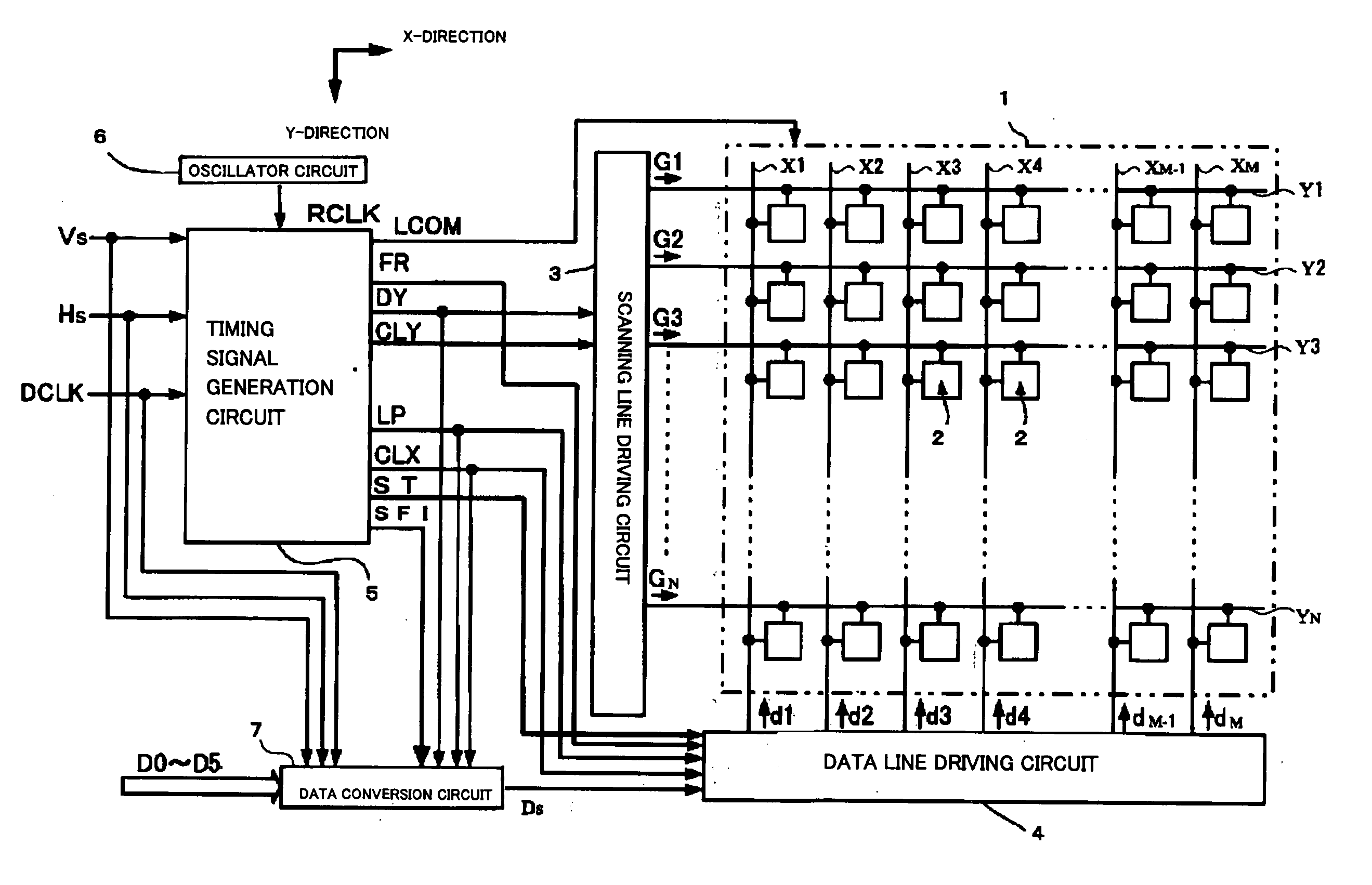
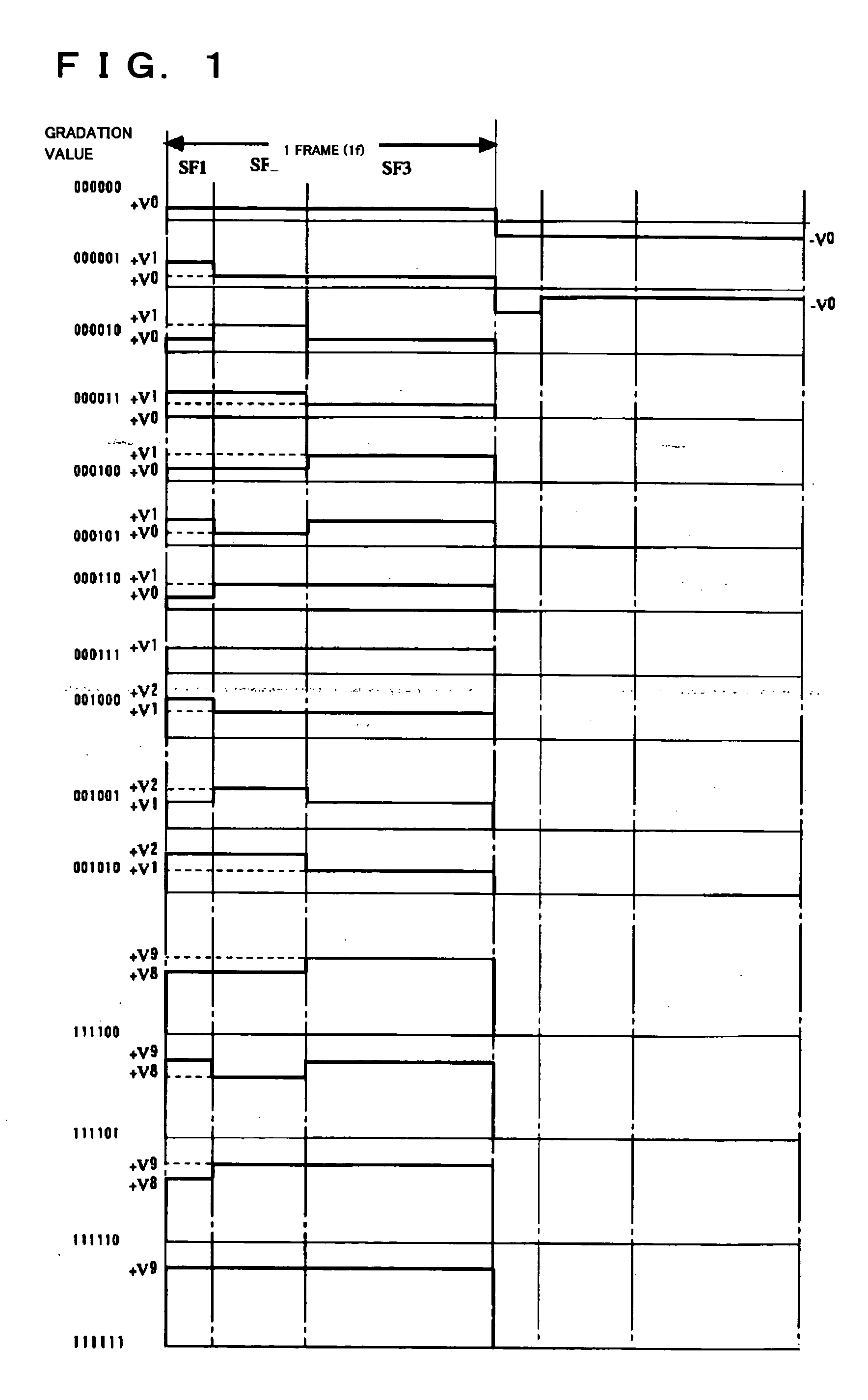
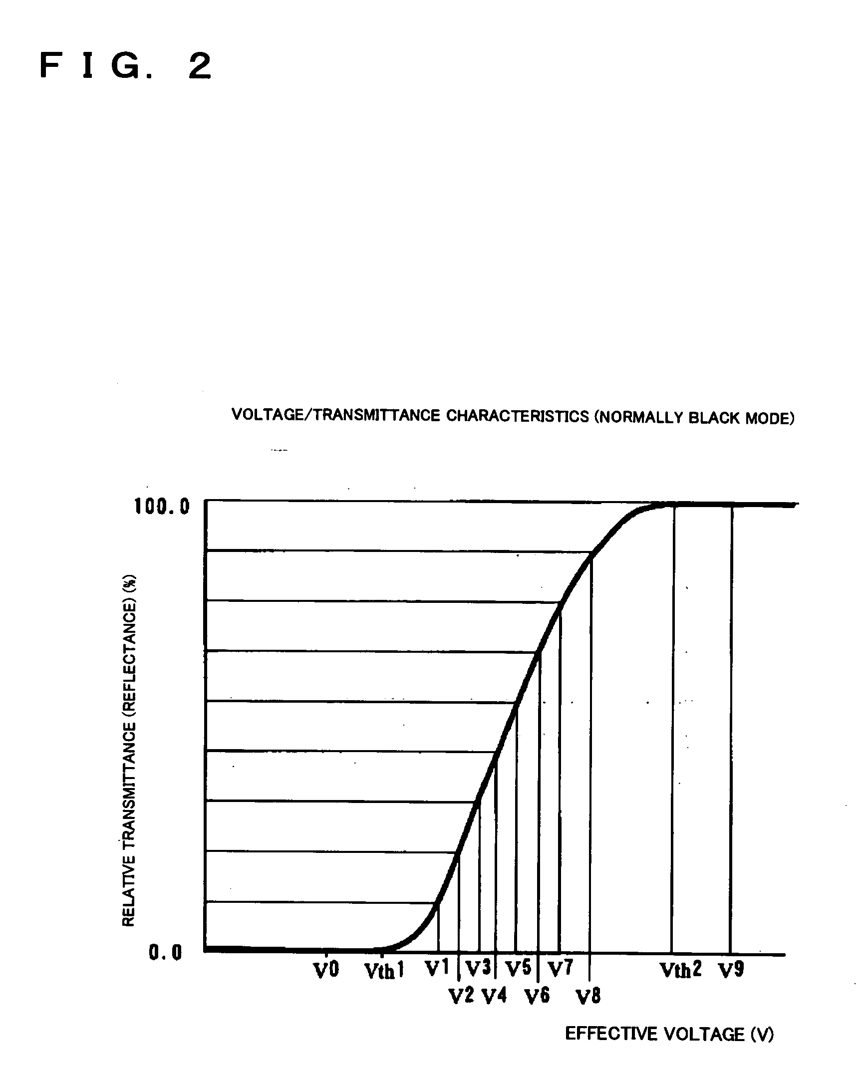
[0035] Before specifically explaining an electro-optical device according to a first exemplary embodiment, the general outlines of sub-field driving in the first exemplary embodiment will be described. FIG. 1 is an illustration for explaining sub-field driving for a liquid crystal element. In FIG. 1, the relationship between a voltage applied to a pixel and gradation data is shown for each sub-field. In general, in a case where a liquid crystal element is used as an electro-optical element in a pixel, data is supplied to the pixel at a voltage level. Also, AC driving in which the level of the voltage polarity is inverted at predetermined intervals (for example, for every one frame) increases the longevity of liquid crystal.

[0036] Gradation data that defines display gradation of a pixel is, for example, 64-gradation data composed of 6 bits, D0 to D5. One frame (1 f) is composed of three sub-fields, SF1 to SF3. In the relationship with gradation to be ...

second exemplary embodiment

[0064] Second Exemplary Embodiment

[0065] FIG. 10 is an illustration for explaining sub-field driving according to the second exemplary embodiment. In FIG. 10, the relationship between a voltage applied to a pixel and gradation data is shown for each sub-field. The sub-field driving in the second exemplary embodiment realizes 64-gradation display by five sub-fields, SF1 to SF5 using five voltage values V0 to V4. One frame (1 f) is composed of five sub-fields SF1 to SF5. In the relationship with gradation to be displayed, the sub-fields SF1, SF2, SF3, SF4, and SF5 basically have lengths (display periods) provided with weights of 1:1:2:4:8, respectively. However, weighting for the sub-fields SF1 to SF5 may be appropriately adjusted in accordance with the characteristics of liquid crystal. As shown in a voltage setting table in FIG. 11, a combination of voltages for the series of sub-fields SF1 to SF5 is selected from among the five voltage values V0 to V4 in accordance with 6-bit grada...

third exemplary embodiment

[0067] Third Exemplary Embodiment

[0068] FIG. 12 is an illustration for explaining sub-field driving according to the third exemplary embodiment. In FIG. 12, the relationship between a voltage applied to a pixel and gradation data is shown for each sub-field. The sub-field driving in the third exemplary embodiment realizes 64-gradation display by seven sub-fields SF1 to SF7 using five voltage values V0 to V4. One frame (1 f) is composed of seven sub-fields, SF1 to SF7. In the relationship with gradation to be displayed, the sub-fields SF1, SF2, SF3, SF4, SF5, SF6, and SF7 basically have lengths (display periods) provided with weights of 1:1:1:1:4:4:4, respectively. However, weighting for the sub-fields SF1 to SF7 may be appropriately adjusted in accordance with the characteristics of liquid crystal. As shown in a voltage setting table in FIG. 13, a combination of voltages for the series of sub-fields SF1 to SF7 is selected from among the five voltage values V0 to V4 set as in the sec...


PUM

PropertyMeasurementUnit
relative transmittanceaaaaaaaaaa
transmittanceaaaaaaaaaa

Abstract

To enhance the gradation characteristics of sub-field driving in order to further enhance the display quality one frame is divided into a plurality of sub-fields SF1 to SF3. Voltage values V, as voltage data for the corresponding sub-fields that is supplied to pixels, are selected from among voltage values V0 to V9 in accordance with gradation data D0 to D5. Gradation display of the pixels is performed by supplying the voltage values V set for the corresponding sub-fields to the pixels. The voltage values V are selected in such a manner that the amount of change in voltages between adjacent sub-fields is one step level or less. Thus, the amount of change in voltages between adjacent sub-fields is minimized.

Description

[0001] 1. Field of Invention[0002] The present invention relates to a driving method for an electro-optical device, an electro-optical device, and an electronic apparatus, and more particularly, to gradation control by sub-field driving.[0003] 2. Description of Related Art[0004] In order to exploit the merits of pulse width modulation and voltage modulation, gradation display technologies using these modulation systems at the same time have been proposed in the related art. For example, Japanese Unexamined Patent Application Publication No. 5-100629 discloses a technology, in an active matrix electro-optical device, of variably setting the width and height of voltage pulses in accordance with gradation data and supplying the pulses to pixels. Also, Japanese Unexamined Patent Application Publication No. 2001-100700 discloses a technology, for sub-field driving, which is a type of pulse width modulation system, of assigning weights to sub-fields by variably setting the levels of a plu...

Claims


Application Information

Patent Timeline
Patent Type & Authority Applications(United States)
IPC IPC(8): G09G3/20G02F1/133G09G3/30G09G3/32G09G3/36G09G5/10H01L51/50H05B33/14
CPCG09G3/2022G09G3/2081G09G3/3233G09G3/325G09G2320/0276G09G3/3648G09G2300/0842G09G2320/02G09G3/3614
Inventor ITO, AKIHIKO
Owner SEIKO EPSON CORP
Why Eureka
Try Eureka