Adaptive packet routing

Inactive Publication Date: 2004-07-29
LUCENT TECH INC
View PDF12 Cites 51 Cited by
  • Summary
  • Abstract
  • Description
  • Claims
  • Application Information

AI Technical Summary

Problems solved by technology

Though still in widespread use, `pinging` has a number of serious drawbacks as a means for determining link and router latencies (packet transit and processing delays).
First, the receipt and processing of the ping and the generation of the echo-reply by the recipient requires a variable amount of processing time, dependant upon the instantaneous processing load of the recipient.
Second, the receipt and processing of the echo and the computation of the transit time requires a variable amount of processing time at the sender, which also depends upon the instantaneous processing load of the sender and adds to the apparent latency of the network elements involved.
Fourth, pinging using hop-by-hop protocols will poorly represent the latency of an end-to-end connection established under the ATM protocol since the route negotiated for the ATM message is likely to be different to that taken by the ping.
Fifth, pining is highly wasteful of network resources because:
(ii) though a control packet carrying a ping or echo may transit many intermediate

Method used


Image

  • Adaptive packet routing
  • Adaptive packet routing
  • Adaptive packet routing

Examples


Embodiment Construction

[0034] Having broadly portrayed the nature of the present invention, examples of the implementation of the invention will now be indicated by way of illustration only. The examples will be described with reference to the accompanying drawings in which:

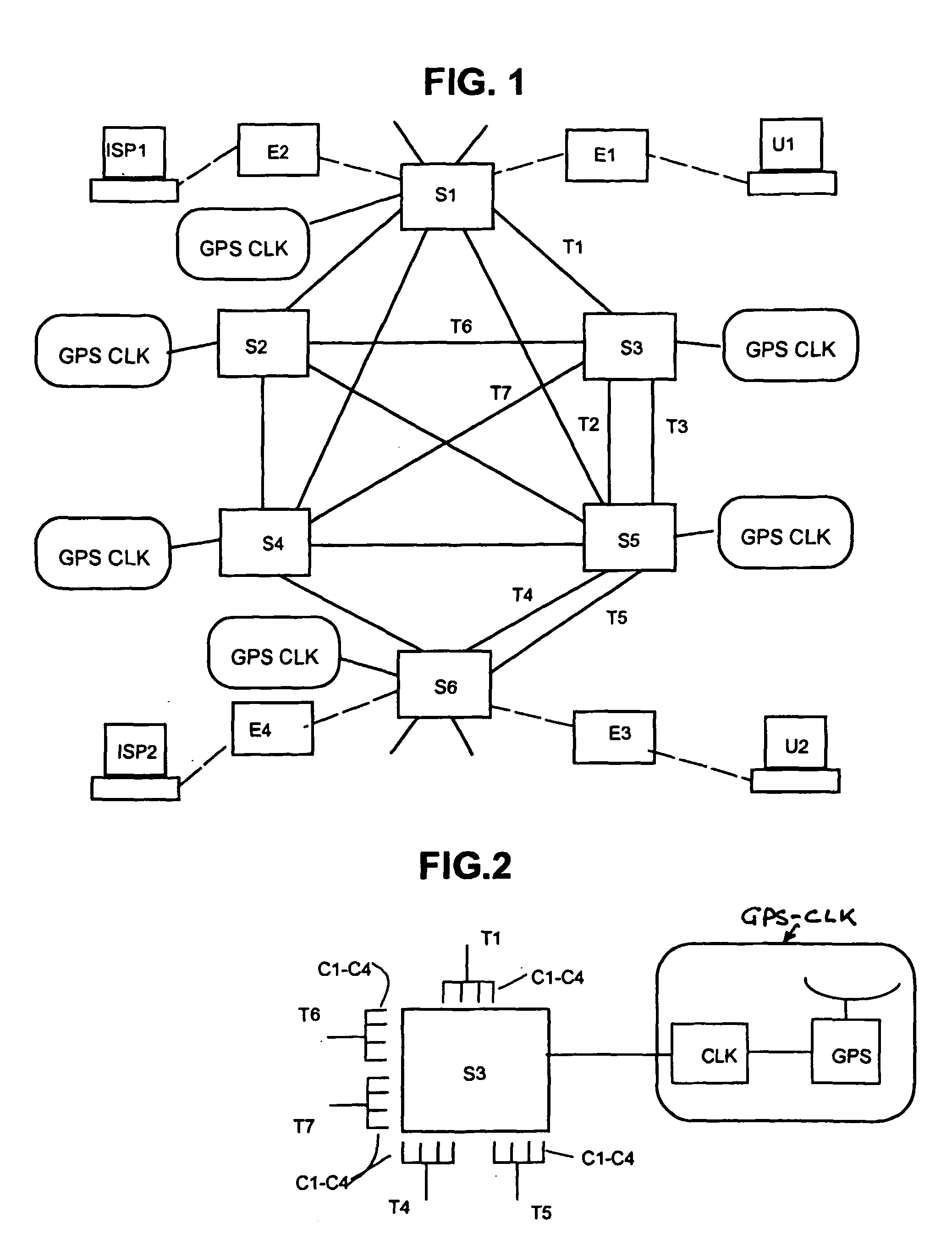
[0035] FIG. 1 is a diagram of a group of interconnected switches that forms part of a telecommunications network of the first example.

[0036] FIG. 2 is a diagram showing one of the switches of the network of FIG. 1, together with its connecting links, in more detail.

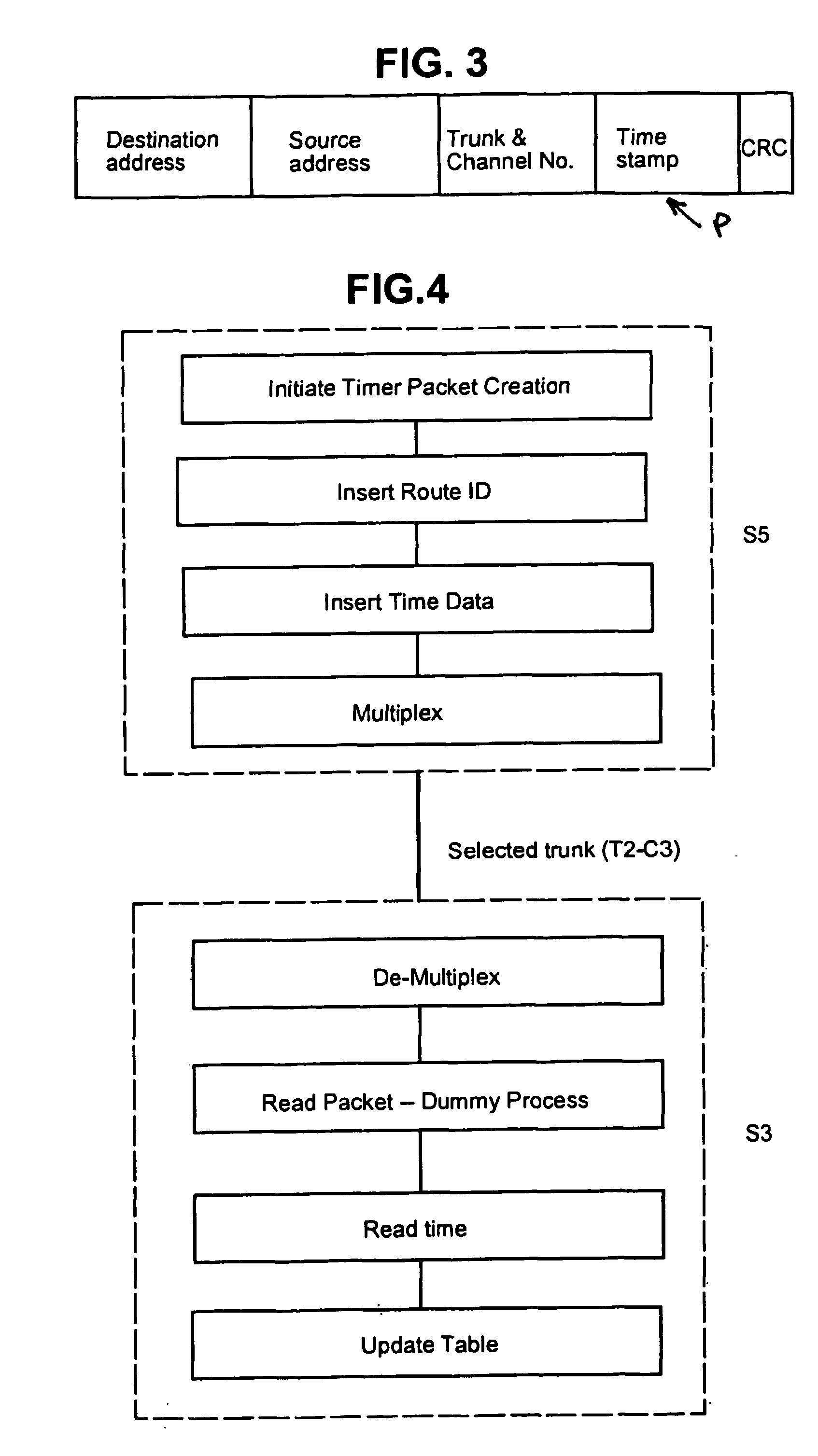
[0037] FIG. 3 is a diagram illustrating the structure of a timer packet employed in the first example.

[0038] FIG. 4 is a flow diagram illustrating the procedure by which a timer packet is generated and accepted by interconnected switches of the first example.

[0039] FIG. 5 is an example of a look-up table that is automatically built and maintained at each switch of the network for the purpose of intelligent routing.

[0040] FIG. 6 is a schematic diagram of a switch of the secon...


PUM


Abstract

A method of determining the latency of a route in a packet-switched network, a packet switch for use in such a method and network and a packet-switched network are disclosed. Preferably, each switch maintains a routing table that records the latency of the routes accessible by that switch. Each switch also preferably has a GPS-based universal time clock which it employs to time the transmission and arrival of identifiable timing packets, these times being used to compute route latency and to up-date the routing tables. In one example (<cross-reference target="DRAWINGS">FIG. 1</CROSS-REFERENCE>) a packet-switched network has a plurality of switches (S1-S6) interconnected by links or trunks (T1-T7). A local GPS-base clock (GPS CLK) is connected to each switch (S1-S6) to enable the accurate timing of transmission and reception of identifiable timing packets in accordance with a system-wide universal timing standard.

Description

[0001] This invention relates to means for or associated with adaptive routing of packets, cells, data, messages or sessions in telecommunications and / or computer networks covering large geographical areas. It also relates to network management systems for such networks employing adaptive routing.[0002] The term `adaptive routing` indicates that the route taken by packets across the network takes account of varying conditions within the network, such as delays, faults, congestion, etc. The invention is suited for use in packet-switched networks that use hop-by-hop / packet-by-packet routing protocols (for example IP or Internet Protocol) with store-and-forward techniques, as well as in networks where the complete route is negotiated at the start of a session and maintained throughout the session (for example ATM or Asynchronous Transfer Mode protocols).[0003] The invention is also concerned with means for determining link and / or router latencies in a network and for using such determi...

Claims


Application Information

Patent Timeline
IPC IPC(8): H04L45/121
CPCH04L41/5009H04L41/509H04L45/26H04L45/121H04L45/12
Inventor MARTIN, ANDREW LOUIS
Owner LUCENT TECH INC
Why Eureka
Try Eureka