Hydraulic/pneumatic apparatus

a technology of hydraulic/pneumatic actuator and actuator, which is applied in the direction of fluid coupling, shutter/movable grille, servomotor, etc., can solve the problems of not ensuring swimming pools, severe damage to the cover slats, and the need to overcome the passive force during retraction

Inactive Publication Date: 2004-07-29
LAST HARRY L
View PDF5 Cites 42 Cited by
  • Summary
  • Abstract
  • Description
  • Claims
  • Application Information

AI Technical Summary

Problems solved by technology

Such passive force systems also have a disadvantage in that the passive force must be overcome during retraction.
This is important because if the cover does not feed properly through the aperture, and becomes obstructed or jams, the cover would continue to unwind "crumpling" and expanding diametrically and underneath the lid causing severe damage to the cover slats.
Also Health and Safety inspectors in many jurisdictions in the United States and elsewhere as well as insurance companies, do not allow or will not insure swimming pools which have underwater apertures that can entrap a swimmer.
Another problem with slatted and other buoyant pool cover systems that emerge from an underwater trench in a pool floor or an underwater recess in sidewall of a pool, is that the cover initially moves vertically due to buoyancy, and upon breaking the water surface, changes direction due to gravity to float horizontally across the pool surface.
Pre-bending doesn't work when the front / leading edge is a foot or more below the water surface.
In such instance the `pre-bending` and the cover will often "snake" back and forth below the water making direction of travel relative to the vertical upon breaking water surface unpredictable.
Separate gear drive systems for pool cover enclosure lids with associated limit switches governing travel for such a limited distances are costly.
Furthermore, electric drives necessitate the supply of electrical current proximate the swimming pool, creating a shock safety hazard.
Moreover electrical components in a moist pool environment are subject to galvanic corrosion rendering them unreliable over time.

Method used


Image

  • Hydraulic/pneumatic apparatus
  • Hydraulic/pneumatic apparatus
  • Hydraulic/pneumatic apparatus

Examples


Embodiment Construction

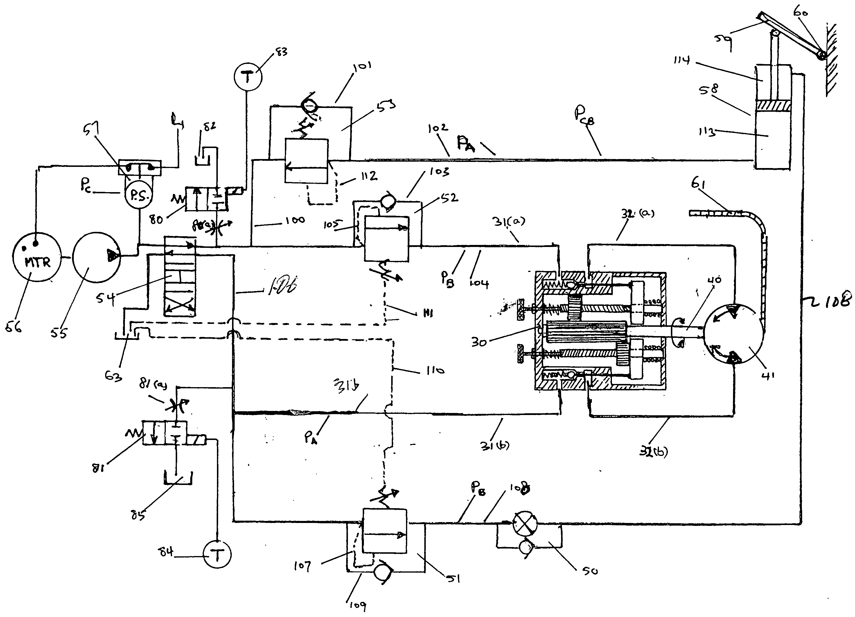
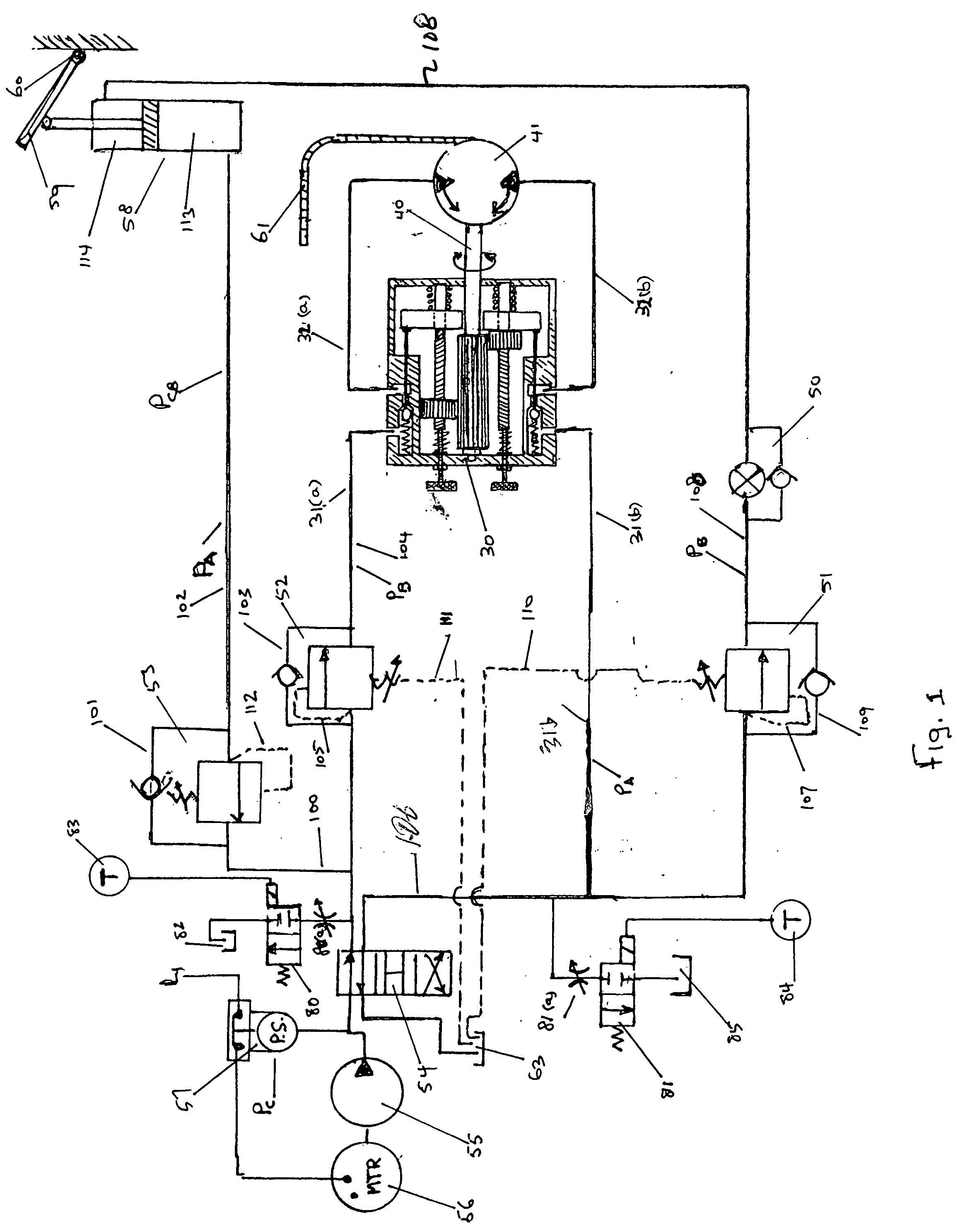
[0028] The invented hydraulic or pneumatic actuation system is presented in context of hydraulically powered automatic swimming pool cover systems such as those Applicant described in U.S. Pat. No. 5,184,357 entitled AUTOMATIC SWIMMING POOL COVER WITH A DUAL HYDRAULIC DRIVE SYSTEM, and U.S. Pat. No. 5,546,751 entitled ANTI-CAVITATION MANIFOLD FOR DRIVE COUPLED, DUAL MOTOR, REVERSIBLE HYDRAULIC DRIVE SYSTEMS, modified for driving buoyant slatted or floating pool cover systems, both of which are incorporated herein reference.

[0029] Looking at FIG. 1, when operating a buoyant slatted or floating cover system in conjunction with a lid covering system, it is important to ensure that the lid 59 is first fully opened before the cover 61 is allowed to move from its fully retracted position. Likewise, it is important assure that the lid 59 has not drifted closed before retracting the cover 61 from its fully extended position covering the pool.

[0030] The invented hydraulic / pneumatic actuation...


PUM


Abstract

An invented fluidic (hydraulic / pneumatic) actuation system is described wherein bidirectional, hydraulic / pneumatically driven elements of multiple components in a common hydraulic / pneumatic circuit inherently provide increases in pressure upon reaching mechanical end points limiting, arresting or stopping further mechanical movement or travel of the driven element of any particular component that switches a sequencing valve system and / or electro-hydraulic / pneumatic pressure switches for directing hydraulic / pneumatic power to other hydraulically / pneumatically driven components in the hydraulic / pneumatic circuit in a timed, sequenced and velocity controlled manner.

Description

[0001] This application relates to U.S. Provisional Patent Application Serial No. 60 / 440,667 filed Jan. 15, 2003 entitled APPARATUS AND METHOD FOR OPENING AND CLOSING A POOL COVER DRIVE CHAMBER, which is incorporated herein by reference in its entirety, and claims any and all benefits to which it is entitled thereby.[0002] This application is also a continuation-in-part of co-pending U.S. patent application Ser. No. 09 / 829,801 filed Apr. 10, 2001 entitled AUTOMATIC POOL COVER SYSTEM USING BUOYANT-SLAT POOL COVERS [PUB. APP. NO. 20020046817][0003] 1. Field of the Invention[0004] This invention relates to a hydraulic or pneumatic actuation system for switching hydraulic / pneumatic power to different hydraulically / pneumatic driven components of automatic swimming pool cover systems in a timed, sequenced, and velocity controlled manner. The invented system is particularly appropriate for passively responding buoyant slat pool cover systems.[0005] 2. Description of the Prior Art[0006] Aut...

Claims


Application Information

Patent Timeline
Patent Type & Authority Applications(United States)
IPC IPC(8): E04H4/08E04H4/10F15B11/20F16D31/02
CPCE04H4/082E04H4/101E06B2009/6881F15B2211/783F15B2211/20515F15B2211/7058F15B11/20
Inventor LAST, HARRY L.
Owner LAST HARRY L
Why Eureka
Try Eureka