
Stage counter mass system

a counter mass and stage technology, applied in the field of stages, can solve the problems of affecting the stability of the system,

Inactive Publication Date: 2004-08-12
NIKON CORP
View PDF13 Cites 11 Cited by
  • Summary
  • Abstract
  • Description
  • Claims
  • Application Information

AI Technical Summary

Benefits of technology

[0011] In another aspect of the present invention a control method is provided for maintaining a center of gravity for a stage and a countermass system comprising a moving stage and at least two countermasses having different target positions. The method includes calculating the target positions for the at least two countermasses according to a position of the stage. The calculating step allows for a weight factor to trade off torque cancellation for reduced countermass stroke. The method of this aspect of the present invention further includes pushing the at least two countermasses towards the different target positions.
[0016] In another aspect of the present invention, an exposure apparatus is provided. In the exposure apparatus, an illumination system is provided for projecting radiant energy through a mask pattern on a reticle. A system reduces a stroke of at least two countermasses in an assembly comprising at least one moving stage and the at least two countermasses. The radiant energy is projected on a wafer which is positioned on the at least one moving stage. The system includes a controller for calculating a target position for the at least two countermasses according to a position of the at least one stage and a motor for pushing the at least two countermasses towards the target position based on the calculating.

Problems solved by technology

The vibration generated by the driving reaction of the stage is transmitted to the structural body, and the vibration is also transmitted to the optical projection system which can cause position shifting of the transfer pattern image and deterioration of contrast.
Recently, modem wafer stages require larger driving forces.
For example, if the stage weighs 180 kg, the driving force required to move this stage at the required acceleration (2 g's) and speed is 2*9.8 m / s.sup.2*180 kg=3528 N. For such a large force, the reaction force shakes the system, and degrades the system accuracy.
It is thus realized that modem lithographic machines of suffer from many problems.
These problems range from stability requirements and more particularly vibrations and shaking of the wafer stage with use of large driving forces.
The shaking and vibrations lead to system degradation including poor lithographic processing of wafers.
The present state of the art, however, is not designed to compensate for these inefficiencies.

Method used


Image

  • Stage counter mass system
  • Stage counter mass system
  • Stage counter mass system

Examples


Embodiment Construction

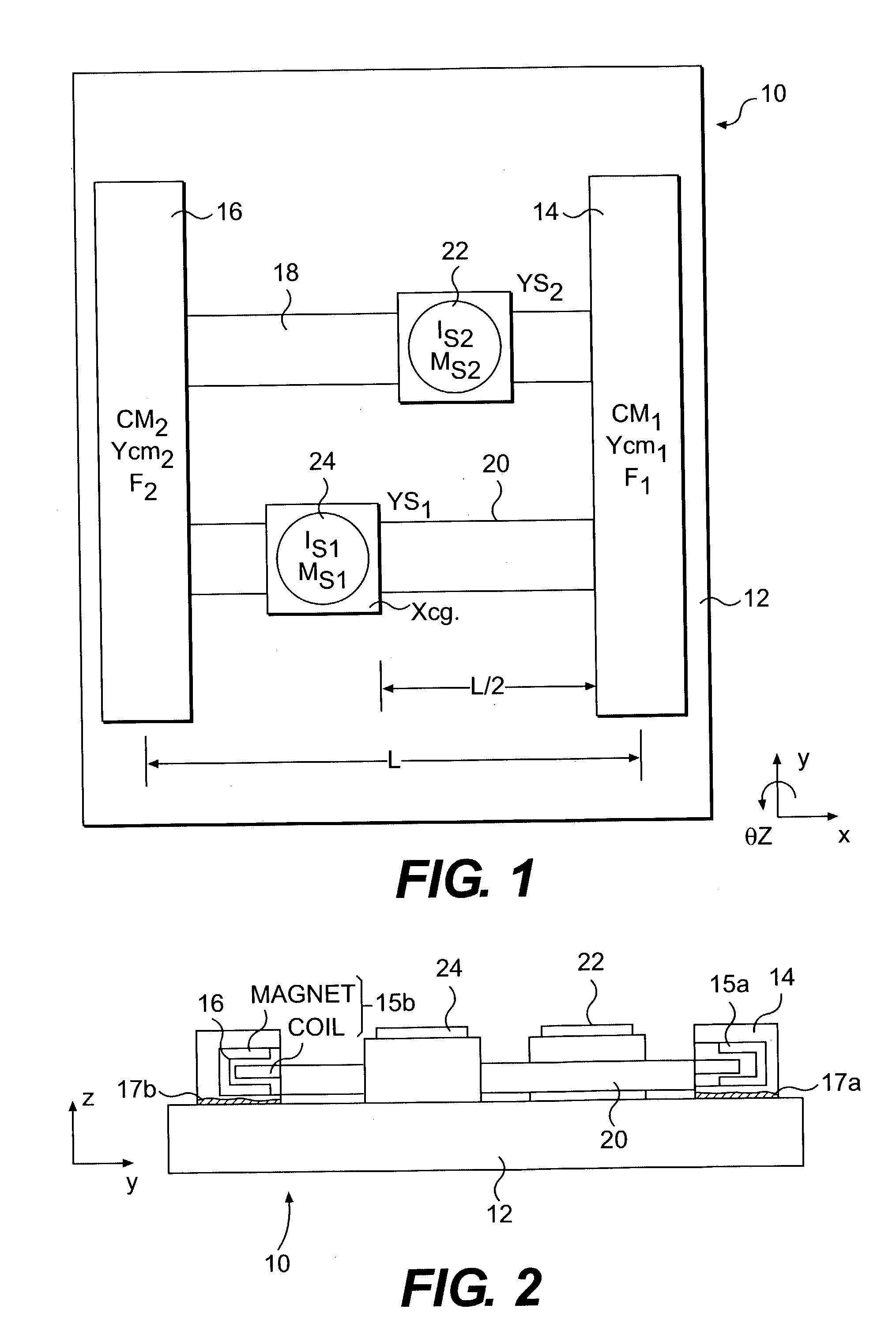
[0029] Referring to FIGS. 1 and 2, there is shown a basic configuration of a twin wafer stage system with two independent 1-dof (degree of freedom) counter masses. The wafer stage system (assembly) 10 includes a base 12, with first and second countermasses 14 and 16 and first and second guidebars 18 and 20 support thereon. It should be understood by one of ordinary skill in the art, however, that countermasses 14 and 16 may also be supported separately from the base 12. First and second wafer stages 22 and 24 are respectively disposed on first and second guidebars 18 and 20.

[0030] As shown, stages 22 and 24 move in the X direction along their respective guidebars 18 and 20. The stages 22 and 24 may also move with the respective guidebars 18 and 20 in the Y direction. In response to these Y motions, countermasses 14 and 16 move in the opposite Y direction. The amount of motion of each countermass 14 and 16 depends on the X position of the stages 22 and 24. The guidebars 18 and 20 may...


PUM


Abstract

A wafer stage countermass assembly generally includes a base supporting one or more stages and first and second countermasses. The first and second stages move in one or more degrees of freedom. The countermasses move in at least one degree of freedom and, under ideal conditions, move to counter the movement of the stages in operation and thus preserve the systems center of gravity to avoid unwanted body motion. However, under actual conditions the countermasses may under travel or over travel their ideal trajectory. To more closely track the ideal trajectory, a controller actuates trim motors to apply small forces to the countermasses to push them towards a reference position in the Y direction. A second embodiment also takes into account the X position the stage(s) to cancel torque.

Description

[0001] 1. Field of the Invention[0002] The present invention generally relates to stages and, more particularly, to the positioning of a counter mass to dampen vibrations caused when the stage is driven.[0003] 2. Description of the Prior Art[0004] When a semiconductor element is manufactured, a projection exposure apparatus is used to transfer an image of a pattern (reticle), used as a mask, onto areas of a resist coated wafer. Two common types of projection systems include batch exposure type step-and-repeat optical projection apparatuses (stepper), and scanning exposure type projection exposure apparatuses (step-and-scan type), which perform an exposure as the reticle and the wafer are synchronously scanned with respect to an optical projection system.[0005] In conventional systems, such as steppers and step and scan systems, for example, the reticle stage which supports and carries the reticle having the original pattern, the wafer to which the pattern is to be transferred, and t...

Claims


Application Information

Patent Timeline
IPC IPC(8): B23Q11/00G03F7/20
CPCB23Q11/0032G03F7/70766G03F7/70725
Inventor BINNARD, MICHAELNOVAK, W. THOMASUETA, TOSHIOYUAN, BAUSAN
Owner NIKON CORP
Learn More