
Infrared image sensor

a technology of infrared image and sensor, which is applied in the field of non-cooling infrared image sensors, can solve the problems of over-cancelling mechanism not working, contributing to chip temperature change, and radiating heat from the whole heat-sensitive parts

Inactive Publication Date: 2004-08-19
KK TOSHIBA
View PDF2 Cites 16 Cited by
  • Summary
  • Abstract
  • Description
  • Claims
  • Application Information

AI Technical Summary

Problems solved by technology

However, such methods have the following problem.
Specifically, the above canceling mechanism does not work, in the case where the temperature of the package on which the chip is mounted has changed, in particular, in the case where the temperature of the chip rapidly changes, such as directly after start of driving the chip.
Further, much heat is radiated from the whole heat-sensitive parts, and contributes to change in the temperature of the chip.
As described above, in conventional thermal infrared image sensors, it is difficult to remove noise components generated by Joule heat in the case where the temperature of the chip rapidly changes, and this is a main cause of lowering the reliability of the sensors.

Method used


Image

  • Infrared image sensor
  • Infrared image sensor
  • Infrared image sensor

Examples


Embodiment Construction

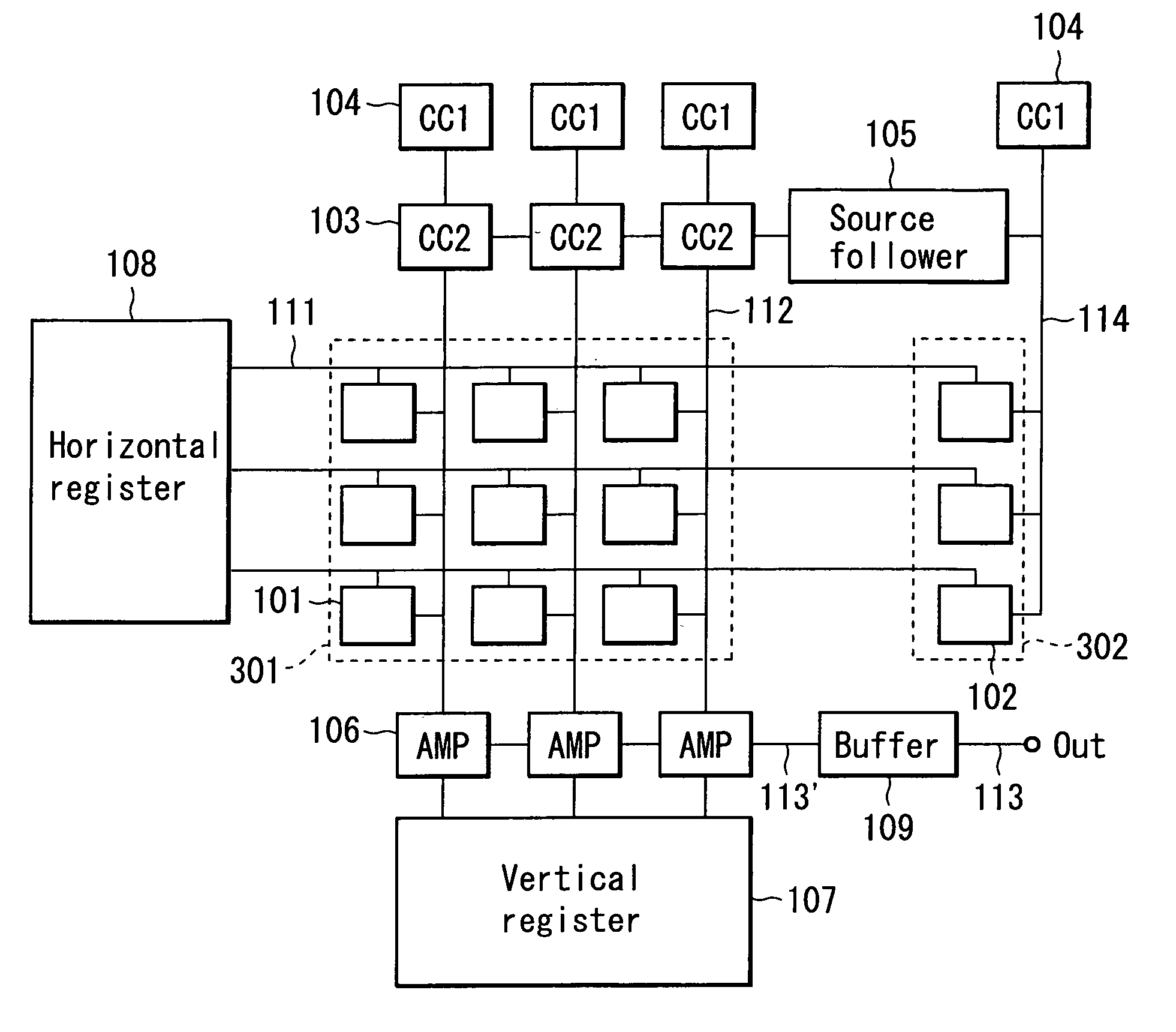
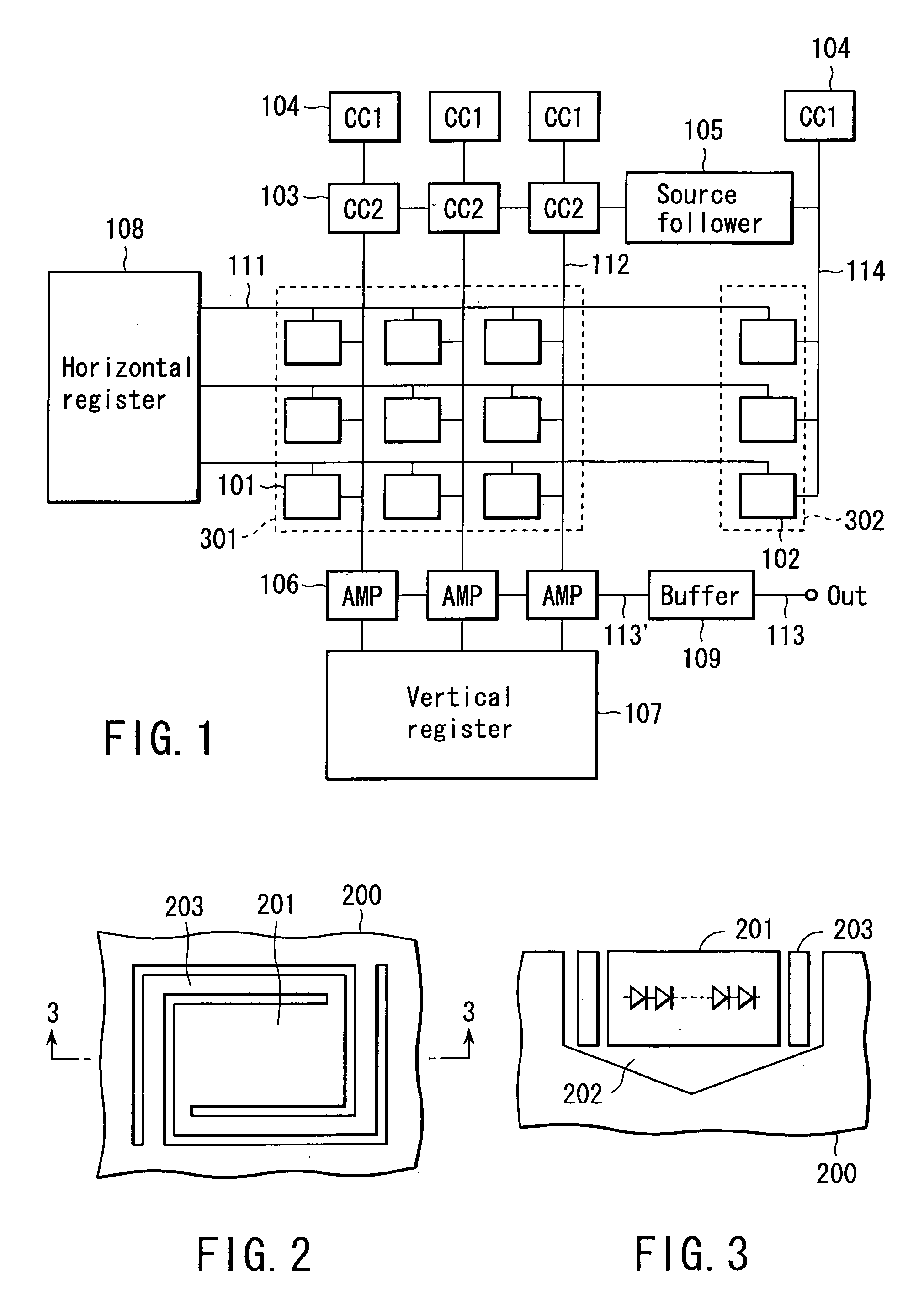
[0039] FIG. 1 is a block diagram illustrating a circuit configuration of a heat-sensitive infrared image sensor according to a first embodiment of the present invention.

[0040] In FIG. 1, reference numeral 101 denotes a heat-sensitive part, which has a structure of absorbing infrared radiation and whose resistance value changes according to heat generated by absorption of infrared radiation. The heat-sensitive parts 101 are arranged in rows and columns extending in an X direction (row direction) and a Y direction (column direction) in an image area on which infrared radiation is made incident. A reference numeral 102 denotes a heat-sensitive part having the same structure as that of the heat-sensitive part 101. The heat-sensitive parts 102 are arranged in a non-image area 302 that is separated from the image area 301 where the heat-sensitive parts 101 are arranged. No infrared radiation is made incident on the non-image area 302.

[0041] The heat-sensitive parts 101 in the image area 3...


PUM


Abstract

An infrared image sensor comprises, a substrate having an image area on which infrared radiation is made incident and an non-image area out of the image area, plural first heat-sensitive parts arranged in rows and columns on the image area, plural second heat-sensitive parts provided in the non-image area so as to correspond to the respective rows of the first heat-sensitive parts in the image area with the same thermoelectric conversion function as that of the first heat-sensitive parts, a bias current supply circuit supplying a bias current to the first heat-sensitive parts and second heat-sensitive parts, an output circuit outputting an electric signal of the first heat-sensitive parts, and a bias current control circuit controlling the bias current to be fed to the first heat-sensitive parts, according to an electric signal of the second heat-sensitive parts.

Description

[0001] This application is based upon and claims the benefit of priority from the prior Japanese Patent Application No. 2003-035570, filed Feb. 13, 2003, the entire contents of which are incorporated herein by reference.[0002] 1. Field of the Invention[0003] The present invention relates to a non-cooled infrared image sensor requiring no cooling device, in particular, an infrared image sensor adopting a method of reading a signal by the passage of a bias current.[0004] 2. Description of the Related Art[0005] Recently, as thermal infrared image sensors which need no cooling devices, infrared image sensors of vanadium oxide bolometer type and BST (Barium-Strontium-Titanate) pyroelectric type have been commercialized. These products comprise heat-sensitive parts which absorb infrared radiation and raise the temperature thereof, support legs for thermally separating the heat-sensitive parts from a silicon substrate, and horizontal address lines and vertical signal lines and the like for...

Claims


Application Information

Patent Timeline
IPC IPC(8): G01J1/02G01J5/24H01L27/14H04N5/33H04N5/335H04N5/357H04N5/369
CPCH04N5/33G01J5/24H04N25/21
Inventor SHIGENAKA, KEITAROIIDA, YOSHINORI
Owner KK TOSHIBA
Learn More