
Apparatus and method for driving a pulsed laser diode

a laser diode and pulsed technology, applied in the direction of electrical apparatus, laser details, semiconductor lasers, etc., can solve the problems of power dissipation, low on-state resistance, and complicated design of pulsed laser drivers

Inactive Publication Date: 2004-08-19
ANALOG MODULES
View PDF13 Cites 51 Cited by
  • Summary
  • Abstract
  • Description
  • Claims
  • Application Information

AI Technical Summary

Problems solved by technology

However, semiconductor laser diodes, particularly high power laser diodes formed from an array of interconnected individual laser diode devices, typically have an extremely low on-state resistance which complicates the design of a good pulsed laser driver.
This approach suffers from two disadvantages, the power dissipation during the interpulse time and the requirement for an opening switch with characteristics of high current, high voltage, fast switch time and low dissipation.
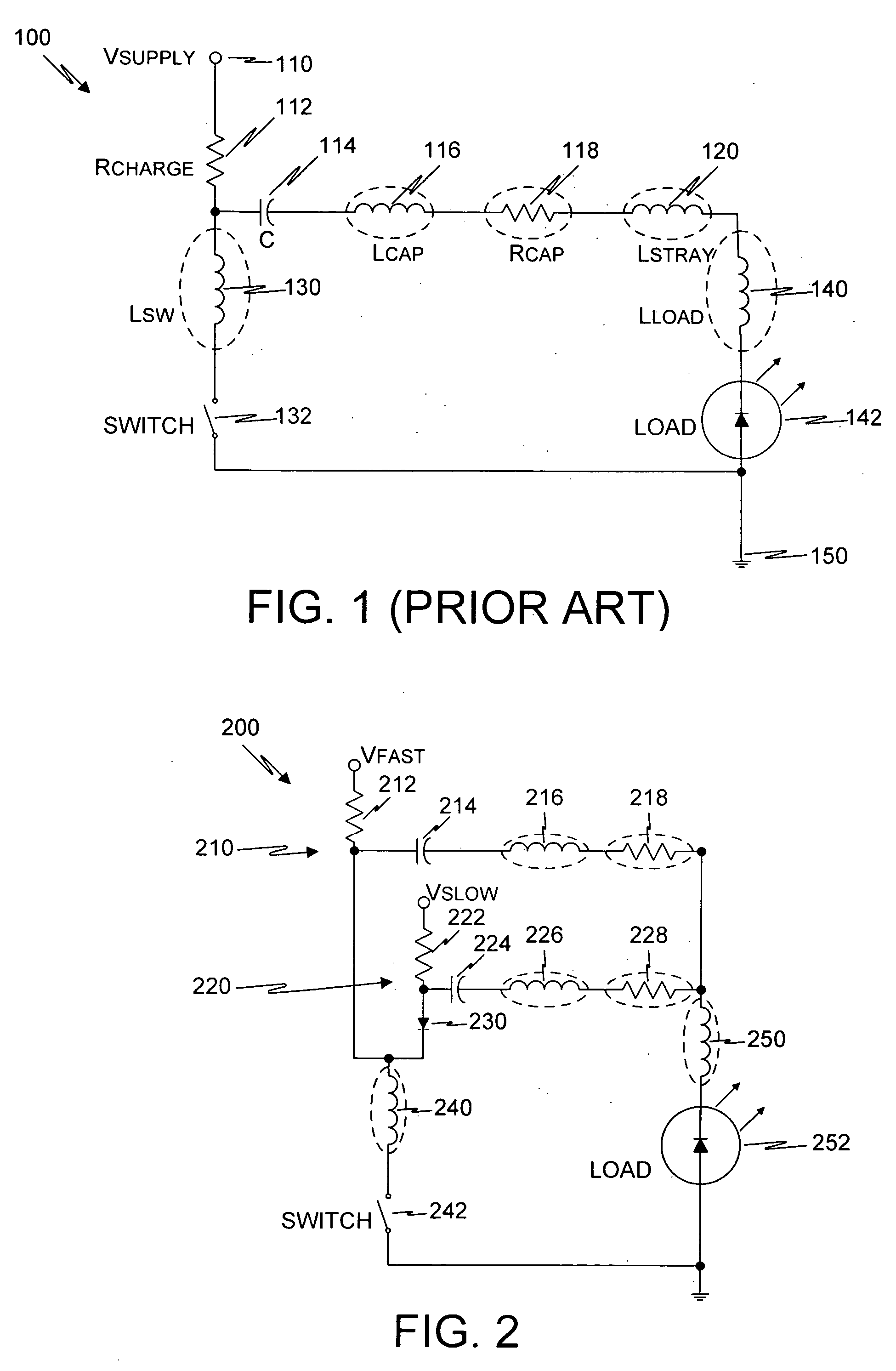
While the voltage source type circuit 100 has the advantages of simplicity and small size, it has the disadvantage of a long L / R time constant which compromises its ability to produce as fast a current pulse risetime as might be desired.
However, the L / R time constant of the circuit limits the current risetime, regardless of the source voltage.
Unfortunately, risetimes faster than 2 .mu.s are sometimes desirable.
While this technique may achieve some improvement, the amount of the improvement is limited by the many inductances in the circuit that are unaffected by the presence of the small capacitor, such as the switch inductance, the load inductance, and the stray inductances.
Unfortunately, these approaches for overcoming the inadequacies of the simple RC-type driver as well as the alternative approaches cause the pulsed laser diode driver to take up more space and / or to be more complex and expensive.

Method used


Image

  • Apparatus and method for driving a pulsed laser diode
  • Apparatus and method for driving a pulsed laser diode
  • Apparatus and method for driving a pulsed laser diode

Examples


Embodiment Construction

[0036] As used herein, the term "laser diode" includes individual diode devices, arrays of diode devices, arrays and / or individual devices connected in parallel, and arrays and / or individual devices connected in series. Laser diodes have an extremely low on-resistance; for example, arrays in common use today typically have a resistance of less than 20 m.OMEGA.. When operating a laser diode in pulse mode, it is desirable that the current driver be capable of driving a pulse having a fast risetime for a given flat top current.

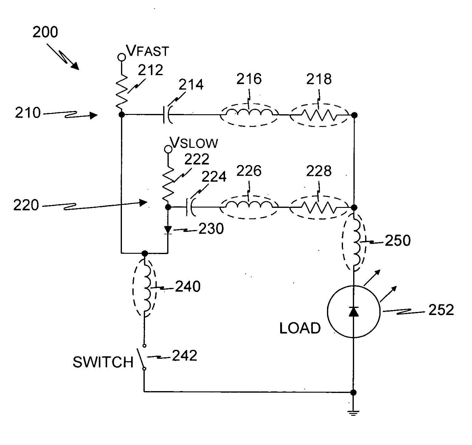
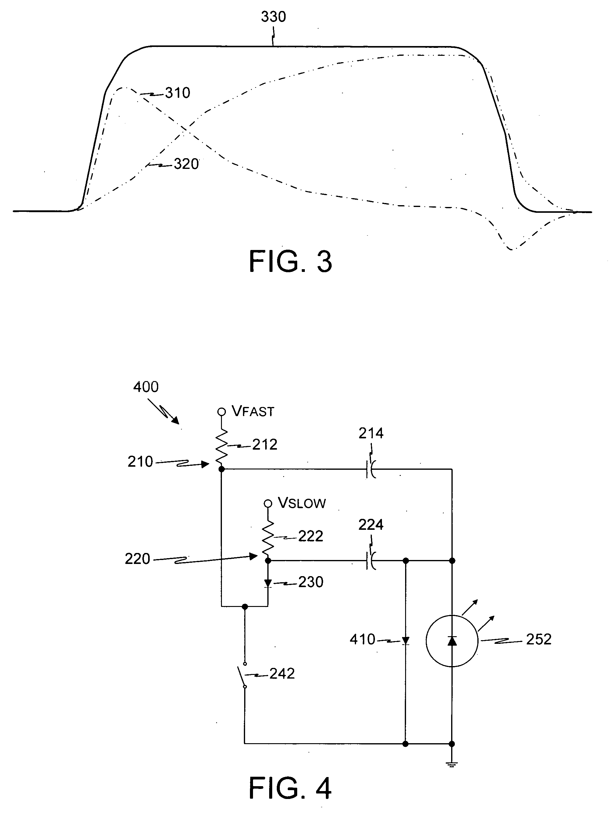
[0037] To achieve both a fast risetime and a desired flat top current pulse, or to be able to independently specify a risetime and pulse width (energy), a supplemental or "fast" voltage discharge stage (or multiple supplemental or "fast" voltage discharge stages) having a faster and shorter voltage discharge characteristic and a higher starting voltage relative to the main or "slow" voltage discharge stage is used in parallel with the slow voltage discharge stage...


PUM


Abstract

To achieve both a fast risetime and a desired flat top current pulse, or to be able to independently specify a risetime and pulse width (energy), a supplemental or "fast" voltage discharge stage (or multiple supplemental or "fast" voltage discharge stages) having a faster and shorter voltage discharge characteristic and a higher starting voltage relative to the main or "slow" voltage discharge stage is used in parallel with the slow voltage discharge stage. The energy storage element of the slow voltage discharge stage has sufficient energy storage at an appropriate voltage level for maintaining the desired flat top current throughout the pulse duration, while the energy storage element of the fast voltage discharge stage has less energy storage capability but a higher starting voltage for achieving the desired fast current pulse risetime. Preferably, a single closing switch is used to couple all energy storage elements to the laser diode to pulse it, although respective separate switches may be used to couple the energy storage elements of the various voltage discharge stages to the laser diode.

Description

[0001] This application claims the benefit of U.S. Provisional Patent Application No. 60 / 438,269, filed Jan. 2, 2003 (Giorgi et al., "Low impedance, fast rise time pulse generator system"), and of U.S. Provisional Patent Application No. 60 / 439,069, filed Jan. 8, 2003 (Giorgi et al., "Low impedance, fast rise time pulse generator system"), which are hereby incorporated herein by reference in their entirety.INVENTORS[0002] David Michael Giorgi, a citizen of the United States resident in Solana Beach, Calif. Jay Philippbar, a citizen of the United States resident in San Clemente, Calif. James Long, a citizen of the United States resident in Ranch Santa Fe, Calif.[0003] 1. Field of the Invention[0004] The present invention relates to pulsed laser diodes, and more particularly to current drivers for laser diodes having fast current pulse risetime.[0005] 2. Description of the Related Art[0006] A laser diode operated in a pulsed mode should be driven by a current driver capable of achievin...

Claims


Application Information

Patent Timeline
IPC IPC(8): H01S3/10H01S5/042
CPCH01S5/0428H01S5/042
Inventor GIORGI, DAVID M.PHILIPPBAR, JAYLONG, JAMES
Owner ANALOG MODULES
Learn More