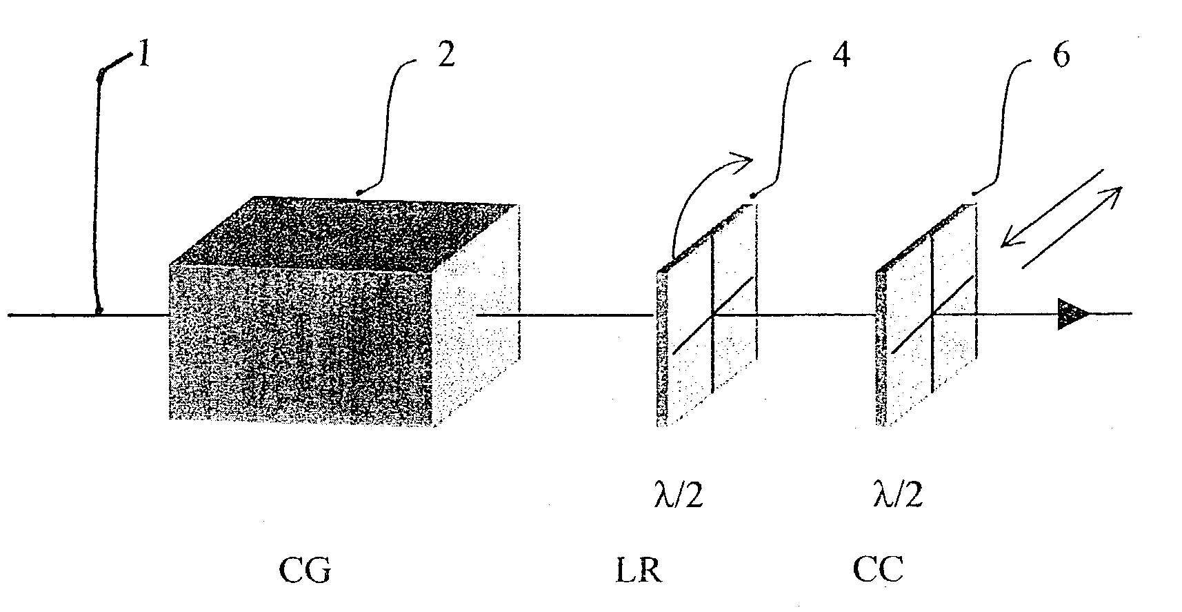
Polarization state conversion in optically active spectroscopy

a technology of optical active spectroscopy and polarization state, applied in the direction of optical radiation measurement, instruments, polarising elements, etc., can solve the problems of tedious and sometimes arbitrary procedures

Inactive Publication Date: 2004-09-02
BIOTOOLS
View PDF13 Cites 16 Cited by
  • Summary
  • Abstract
  • Description
  • Claims
  • Application Information

AI Technical Summary

Problems solved by technology

Such tedious and sometimes arbitrary procedures in order to achieve the des

Method used


Image

  • Polarization state conversion in optically active spectroscopy
  • Polarization state conversion in optically active spectroscopy
  • Polarization state conversion in optically active spectroscopy

Examples


Embodiment Construction

[0041] Optical Offset Elimination in Collinear Scattered Circular Polarization Raman Optical Activity Scattering (SCP-ROA)

[0042] Scattered circular polarization Raman optical activity scattering (SCP-ROA) is defined as the difference in the Raman scattered light intensity from a sample of chiral molecules for alternately or simultaneously analyzed right and left CP scattered Raman light. The incident light is in a fixed unpolarized state. FIG. 4 is a schematic of how the invention would be used in SCP-ROA. Forward scattering is used in this example, but identical considerations apply to other scattering geometry.

[0043] FIG. 4 is a schematic of the device that achieves the balancing of the content of the left and right CP light to a high level of precision that is required for this technique. The arrangement in FIG. 4 achieves this level of precision, in a time-averaged fashion, without any need for the precise adjustment even for incident light having a circularity content of one pe...


PUM


Abstract

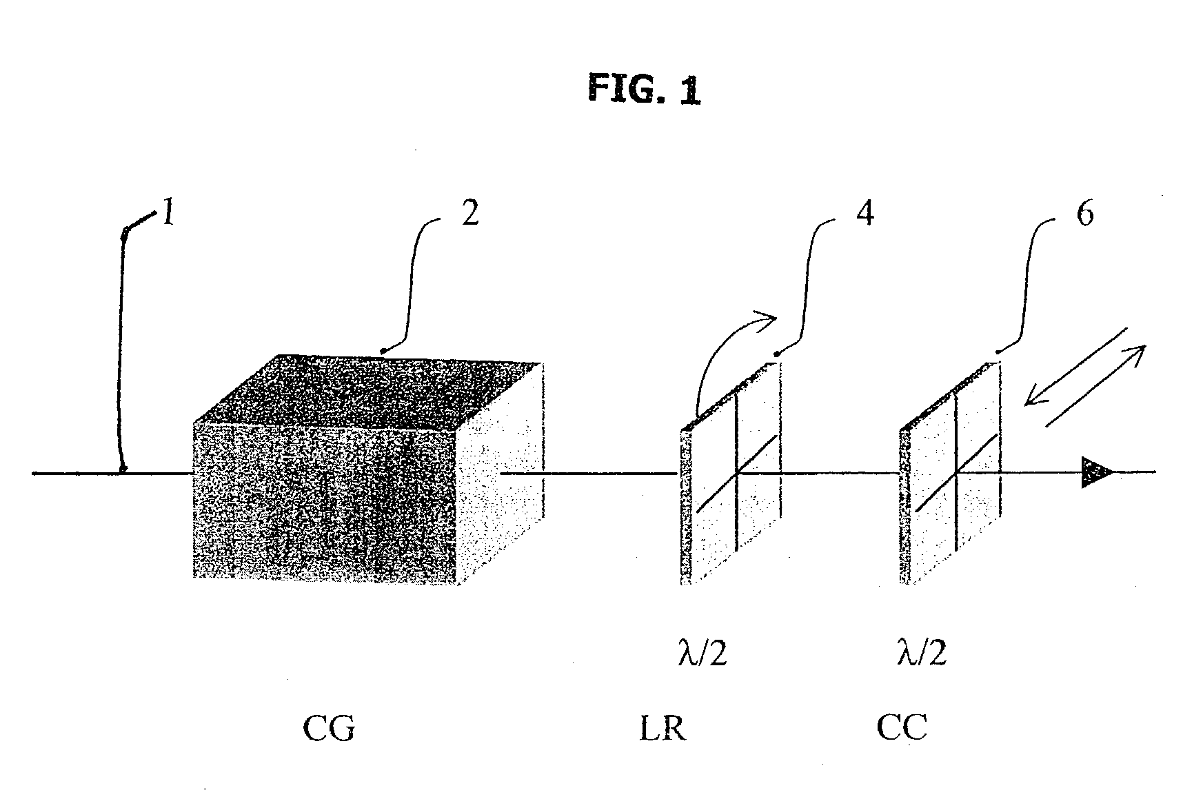
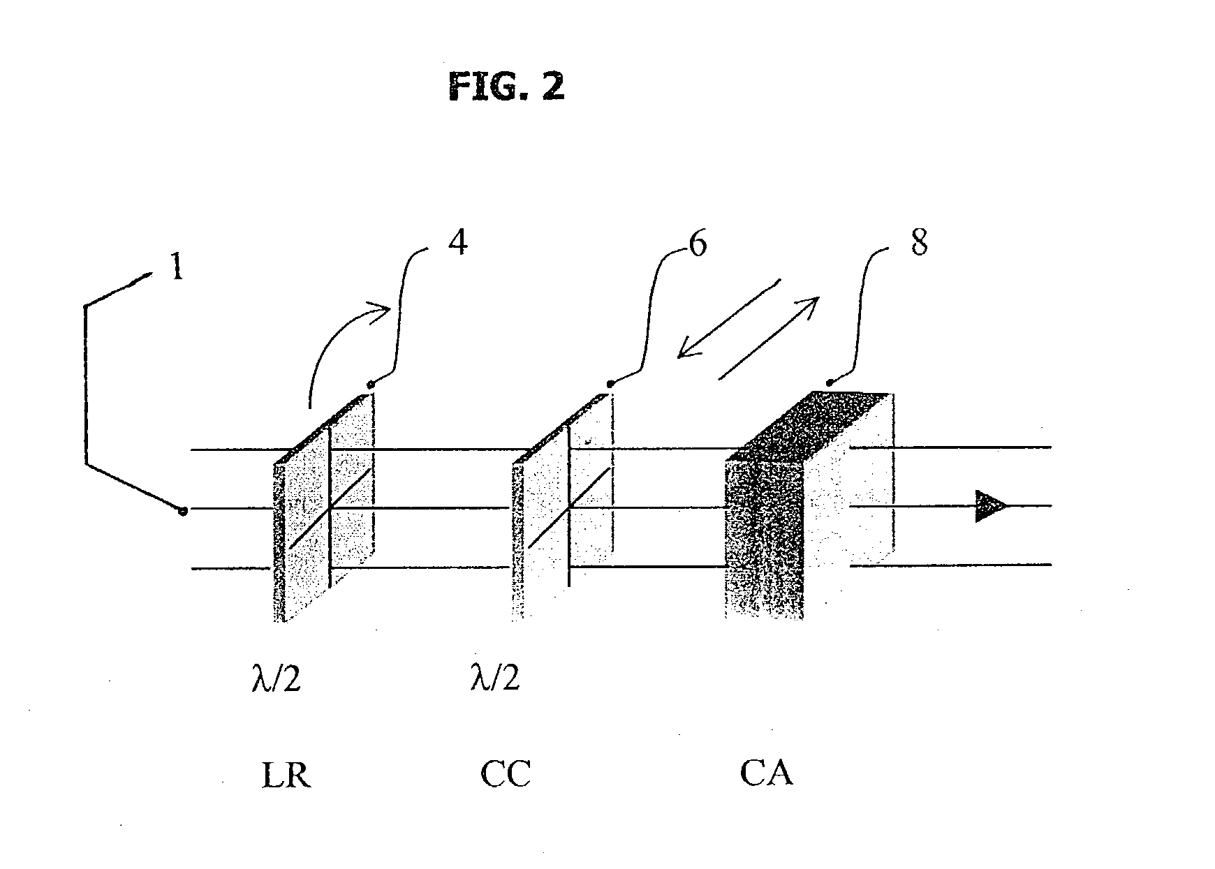
The invention describes a method to eliminate instrumental offset in measurement of optically active scattering and circular dichroism. The method uses the time-average measurement of the light that is systematically transformed by a series of optical devices. The optical devises perform the function of rotating linearly polarized light, interconverting left and right circular polarized light, converting circular polarized light to rotating linear polarized light and converting linear polarized light to alternating left and right circular polarized light.

Description

[0001] This invention deals with the field of spectroscopy and specifically with the application of spectroscopy to measurement of circularly polarized light. More specifically it deals with optical elements that can be inserted into the optical path of either the exciting light or into the optical path of the transmitted or scattered light.[0002] All measurements of various forms of optical activity rely on a small difference in the interaction of the right and left circularly polarized (hereinafter CP) or chiral light with a chiral sample. Typically, the chiral sample consists of molecules that are chiral, i.e., molecules that have non-superimposable mirror images of each other, like a person's left and right hand. There are three areas where this interaction manifests itself in a degree that can be measured. In optically active scattering, a small difference in the intensity for the left or right CP of the scattered light from the sample when the sample is excited with left and r...

Claims


Application Information

Patent Timeline
IPC IPC(8): G02B5/30G02B27/28
CPCG02B27/286G02B5/3083
Inventor HUG, WERNER
Owner BIOTOOLS
Why Eureka
Try Eureka