Self-expanding stent delivery device

a stent and self-expanding technology, applied in the field of self-expanding stent delivery devices, can solve the problems of lumen wall injury, difficulty for medical practitioners in placing the stent exactly as required,

Active Publication Date: 2004-09-16
ANGIOMED GMBH & CO MEDIZINTECHNIK KG
View PDF29 Cites 213 Cited by
  • Summary
  • Abstract
  • Description
  • Claims
  • Application Information

AI Technical Summary

Problems solved by technology

Despite the maturity of the self-expanding stent placement art, there continue to be difficulties for medical practitioners in placing the stent exactly as required.
At this point, the sten

Method used


Image

  • Self-expanding stent delivery device
  • Self-expanding stent delivery device
  • Self-expanding stent delivery device

Examples


Embodiment Construction

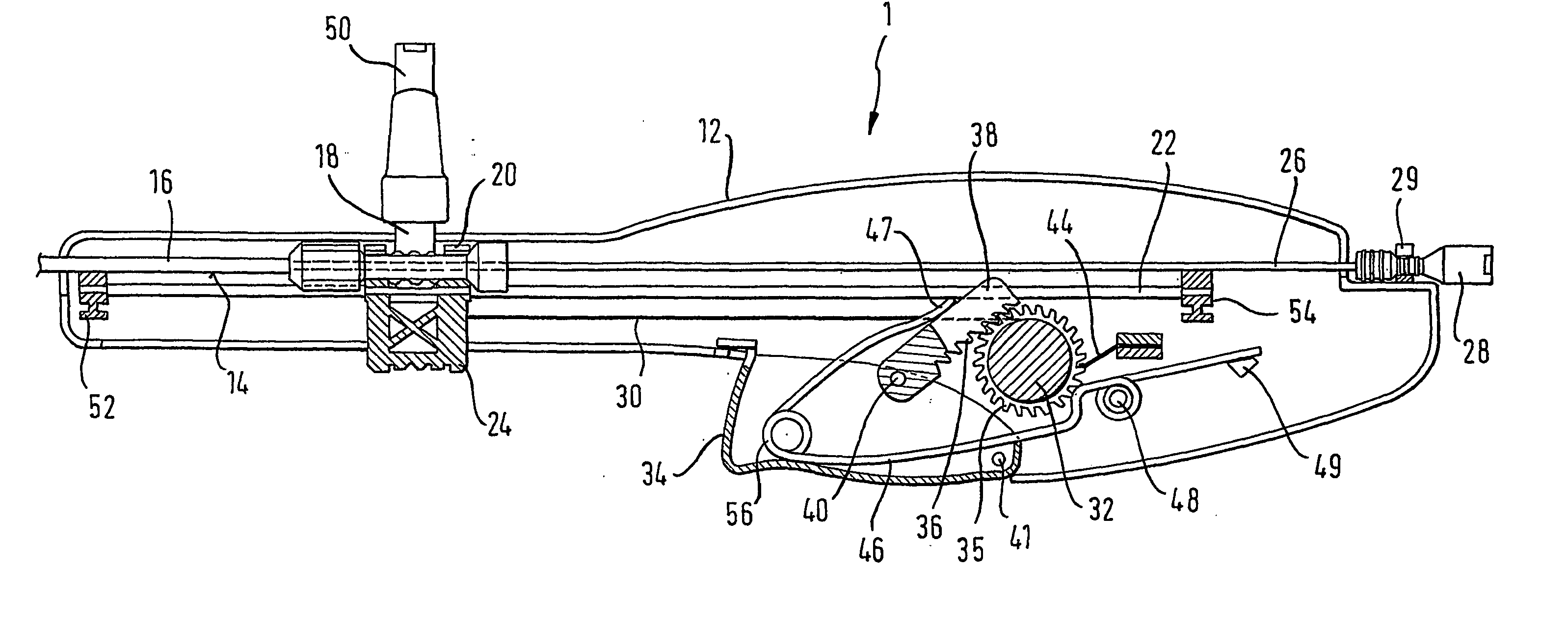
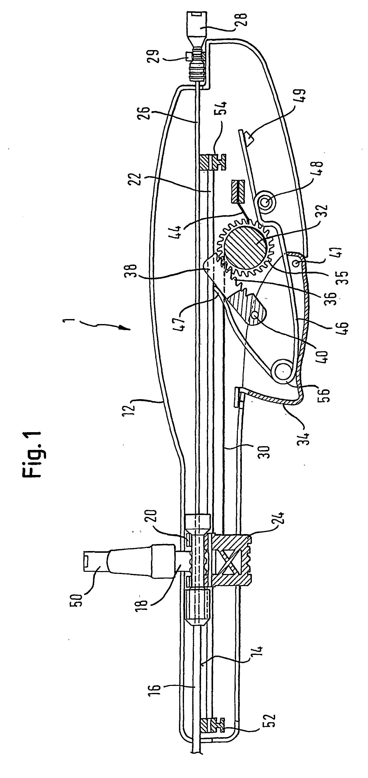
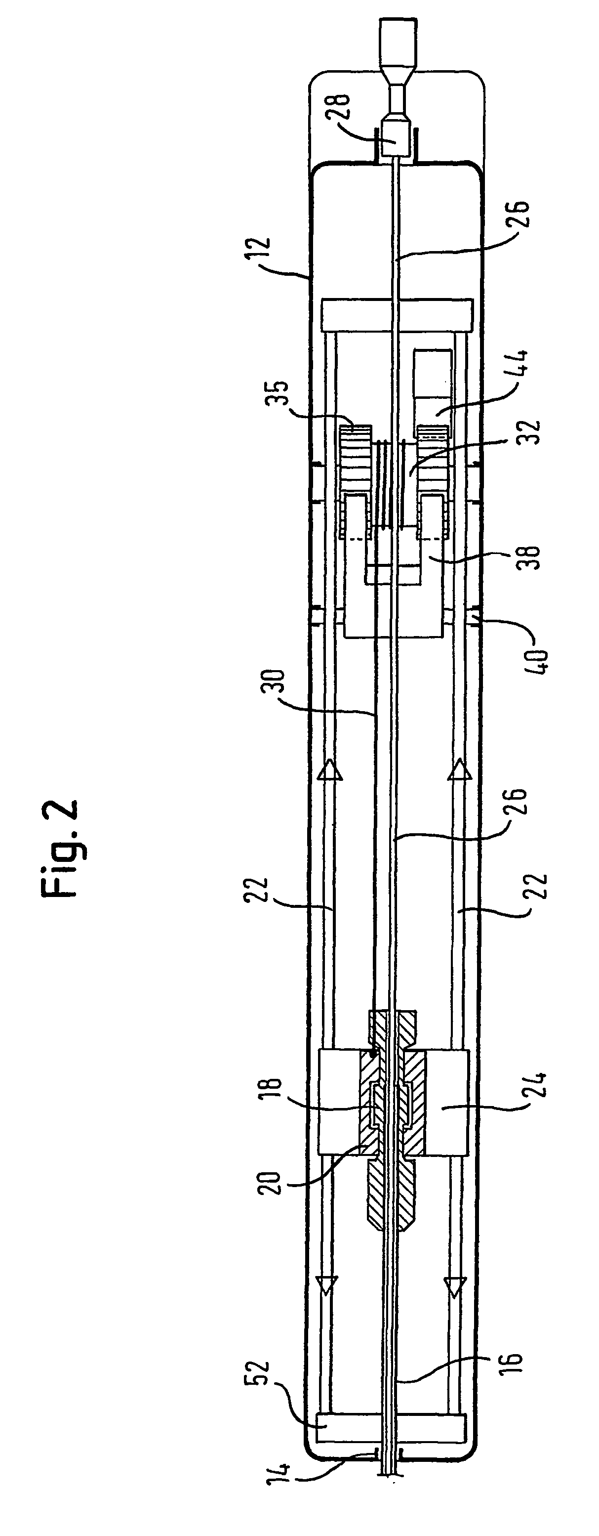
[0027] The drawings are of a preferred embodiment of the invention and FIG. 1 shows one half 12 of a moulded housing of which the other half lies above the plane of the drawing.

[0028] The two housing halves define, in an assembled state, a track 14 in which can be laid the proximal end of a co-axial stent delivery device having an outer tube 16. Track 14 is formed by mating axial recesses in the two housing halves, resulting in a semi-circular channel open to the upper end in FIG. 1 of the housing.

[0029] The proximal end of the outer tube 16 carries a hub 18 which is received within a yoke 20 of a slider 24 which itself runs on a pair of rails 22. The rails 22 are not integral moulded parts of the housing and are held in place by advancing a first one of the rails through a hole (not shown in FIG. 1) and through fixing part 52 and feed hole in slider 24 at the distal end of the housing and into blind hole at fixing point 54 distal from the proximal end of the housing. The distal end...


PUM


Abstract

The present invention relates to a method and device (1) for releasing into the body from a delivery system a medical prosthesis mounted on the delivery system and held by a constraint (16) in a constrained delivery disposition. The device comprises a first abutment (28) for the delivery system, a second abutment (18) for an elongate element (30) to connect the device to the prosthesis constraint, a track (14) for the second abutment (18) to advance along, from a starting point corresponding to constraint of the prosthesis, to a finishing point corresponding to separation of the prosthesis and constraint (16), ratchet means (38) to advance the second abutment (18) progressively, from the starting point to the finishing point, in a plurality of actuation strokes, and is characterised by a full stroke actuator (24), to advance the second abutment (18) all the way from an intermediate point on said track (14) to said finishing point in one single stroke of the said actuator (24), the intermediate point being selectable by the user within a portion of the track (14) which extends over at least half the length of the track.

Description

[0001] 1. Field of the Invention[0002] This invention relates to a device for releasing into the body from a delivery system a medical prosthesis mounted on the delivery system and held by a constraint in a constrained delivery disposition. The device comprises a first abutment for the delivery system, a second abutment for an elongate element to connect the device to the prosthesis constraint, a track for the second abutment to advance along, from a starting point corresponding to constraint of the prosthesis, to a finishing point corresponding to separation of the prosthesis and constraint, and ratchet means to advance the second abutment progressively, from the starting point to the finishing point, in a plurality of actuation strokes.[0003] 2. Description of Related Art[0004] The device is particularly applicable to the release into the body of a self-expanding stent, such as one made from nickel-titanium shape memory alloy. Self-expanding stents usually have a basically cylindr...

Claims


Application Information

Patent Timeline
IPC IPC(8): A61F2/95A61M39/10
CPCA61F2/95A61F2/966A61M39/1011A61F2002/9517A61F2/9517
Inventor DORN, JURGENVOGEL, MICHAEL
Owner ANGIOMED GMBH & CO MEDIZINTECHNIK KG
Why Eureka
Try Eureka