Method for the manufacture of corrugated board

Inactive Publication Date: 2004-09-23
BHS CORRUGATED MASCHEN & ANLAGENBAU
View PDF11 Cites 22 Cited by
  • Summary
  • Abstract
  • Description
  • Claims
  • Application Information

AI Technical Summary

Benefits of technology

0006] The invention is based on the idea that the coatings used for improved printing quality in other fields, for instance in printing special paper or special films for office purposes, can also be used when webs of material of corrugating machines are printed. This is surprising, given the different nature of the starting material. The coating--also called primer--which improves the printing quality results in that the printing ink can be applied accurately a

Problems solved by technology

It is even possible, in particular when an ink jet printer is used, to print a web of single-faced corru

Method used


Image

  • Method for the manufacture of corrugated board
  • Method for the manufacture of corrugated board
  • Method for the manufacture of corrugated board

Examples


first embodiment

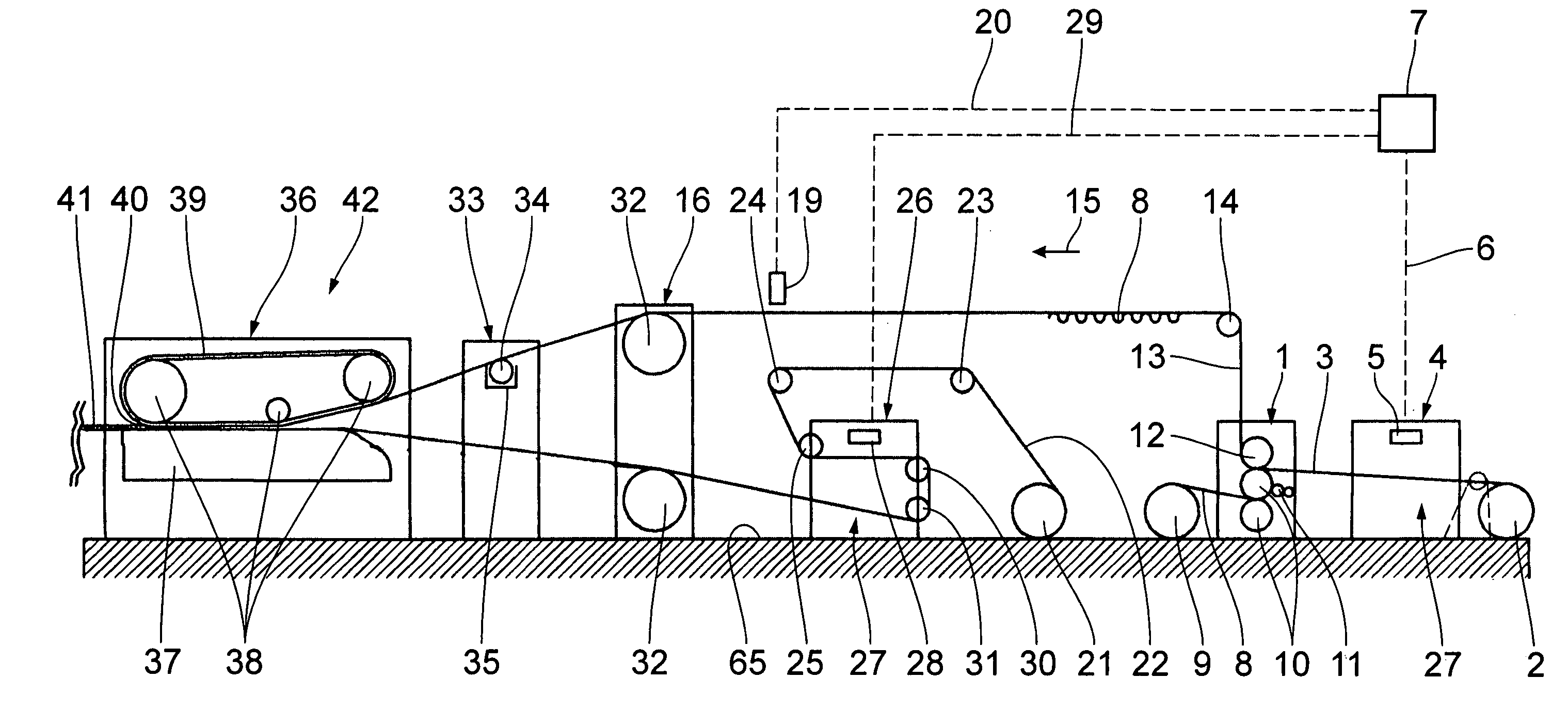
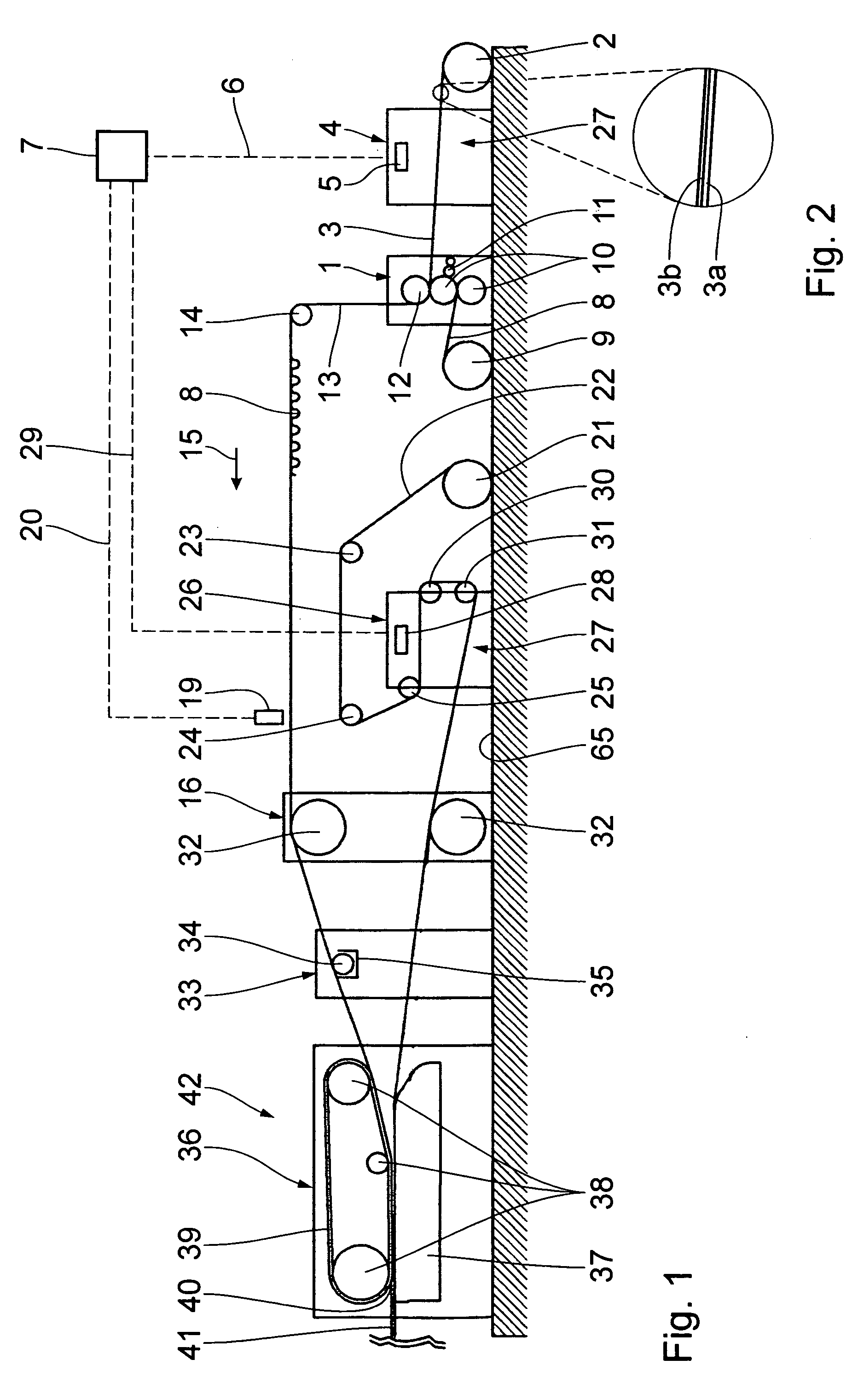
[0020] The following is a description of the invention, taken in conjunction with FIGS. 1 to 6. A corrugating machine as diagrammatically plotted in FIGS. 1 and 6 comprises a machine 1 for the manufacture of single-faced corrugated board. From a first unroll stand 2, a first web of material 3 is fed to the machine 1. The webs of material are continuous paper webs. The web of material 3 constitutes a backer web for the corrugated board manufactured on the machine 1. FIG. 2 is a side view, on an enlarged scale, of the first web of material 3 in detail. It comprises a backer 3a with a primer 3b which improves the printing quality. The backer 3a to primer 3b thickness ratio is not true to scale in FIG. 2. In practice, the primer 3b is substantially thinner as compared to the backer 3a than shown in FIG. 2. The primer 3b must not necessarily be available in a form applied to the web of material 3 when it is rolled up; it can just as well be applied to the web of material 3 later upon unw...

second embodiment

[0039] FIG. 7 illustrates a second part of a corrugating machine according to a FIGS. 8 to 11 illustrate further embodiments of corrugating machines. Components that correspond to those described with reference to FIGS. 1 to 6 have the same reference numerals and are not going to be explained in detail again.

[0040] In the corrugating machine according to the second embodiment, a digital printing system 69 is disposed downstream of the heater (not shown). With no relevant shrinkage of the web taking place between the jobs of printing the web of corrugated board 41 and depositing the cut sheets of corrugated board 62, 67, the readers 19, 44 of the first embodiment can be dropped.

second exemplary embodiment

[0041] In the second exemplary embodiment, a reader 70 is disposed upstream of the lengthwise cutting / grooving unit 46, crosswise scanning the web of corrugated board 41 and recognizing the distribution of printing patterns 43 on the web of corrugated board 41. Signal lines 71, 72 provide for signalling connection of the reader 70 with the lengthwise cutting stations 48. Depending on recognition of the printing patterns 43 by the reader 70, the lengthwise cutting stations 48 are triggered for web sections 52, 53 to be cut, having a width that corresponds to the arrangement of the printing patterns.

[0042] Another reader 73 is disposed between the lengthwise cutting / grooving unit 46 and the cross-cutting unit 54, within its range scanning the web sections 52, 53 of the web of corrugated board in the working direction 15 i.e., lengthwise, and registering the distribution of printing patterns 43 on the web of corrugated board 41 in the working direction 15. A signal line 74 connects the...


PUM

PropertyMeasurementUnit
Angleaaaaaaaaaa
Temperatureaaaaaaaaaa
Environmental propertiesaaaaaaaaaa

Abstract

A web of material serves for use in a corrugating machine for the manufacture of sheets of corrugated board. The corrugating machine comprises at least two unroll stands for unwinding webs of material. A fluting unit serves for the manufacture of at least one corrugated medium from one of the webs of material. A processing equipment serves for uniting the webs of material to form a web of corrugated board. The sheets of corrugated board are cut from the web of corrugated board by means of a cutting unit. A printing system is provided for printing at least one of the webs. The web of material has a coating for improved printing quality. A method for the manufacture of sheets of corrugated board is specified, using such a web of material. The results are sheets of corrugated board with improved imprint.

Description

[0001] 1. Field of the Invention[0002] The invention relates to a method for the manufacture of sheets of corrugated board on a corrugating machine, comprising at least two unroll stands for unwinding webs of material from reels of material; at least one fluting unit for the manufacture of at least one corrugated medium from one of the webs of material; at least one processing equipment for uniting the corrugated medium and at least another web of material to form a web of corrugated board; a cutting station for cutting the sheets of corrugated board from the web of corrugated board; a printing system for printing at least one of the webs.[0003] 2. Background Art[0004] Corrugating machines for the manufacture of single-faced corrugated board or multi-layer corrugated board are for example known from U.S. Pat. No. 5,632,850. Simple and flexible methods of printing webs of corrugated board have not been known.[0005] It is an object of the invention to develop a web of material for the...

Claims


Application Information

Patent Timeline
IPC IPC(8): B31F1/28
CPCY10T156/1025B31F1/2822
Inventor STADELE, NORBERTTITZ, FELIX
Owner BHS CORRUGATED MASCHEN & ANLAGENBAU
Why Eureka
Try Eureka