
Electrophotographic photoreceptor and image forming device

a photoreceptor and photoreceptor technology, applied in the field of electrostatic charge photoreceptors, can solve the problems of light that radiates from the flash lamp (the flash light), leakage of the flash fixing means, and reaches the photoreceptor, and achieves the effect of not reducing the sensitivity of the photoreceptor and its ability to be electrostatically charged

Active Publication Date: 2004-09-23
KYOCERA DOCUMENT SOLUTIONS INC
View PDF0 Cites 9 Cited by
  • Summary
  • Abstract
  • Description
  • Claims
  • Application Information

AI Technical Summary

Benefits of technology

[0012] It is an object of the present invention to eliminate the aforementioned problems, and provide an electrophotographic photoreceptor and an image forming device employing the same that does not generate electrostatic irregularities even if exposed to light leaked from the flash fixing means, and in which the sensitivity of the photoreceptor and its ability to be electrostatically charged do not decrease even with repeated use.
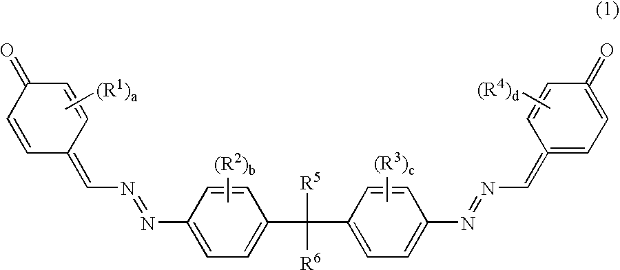
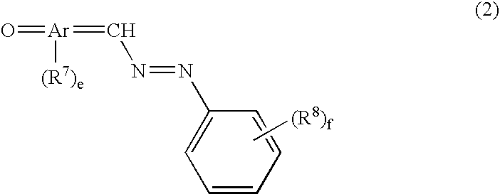
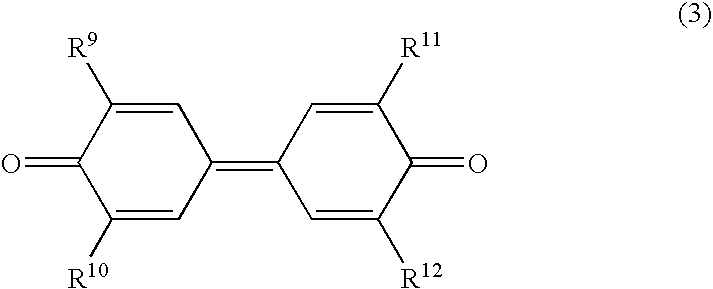
[0013] In order to achieve the aforementioned object, the present inventors have identified a method of effectively controlling the degradation of the photoreceptor due to leaked light by limiting the spectral characteristics of the charge transport agent contained in the photosensitive layer of the electrophotographic photoreceptor to an optimal range.

Problems solved by technology

However, in conventional image forming devices, the light that radiates from the flash lamp (the flash light) leaks from the flash fixing means and reaches the photoreceptor.
Because of this configuration, flash light leakage from the flash fixing means is inevitable, and thus leaked light radiates onto the photoreceptor after the transfer process has been completed.
In addition, the portion of the photoreceptor on which the leaked light has been radiated will not be properly developed, and thus images therefrom will be uneven.
Furthermore, when leaked light is repeatedly radiated onto the photoreceptor, the photoreceptor will become increasingly degraded, and its sensitivity and its ability to be electrostatically charged will decrease.
In addition, the density of the image formed on the recording medium will decrease, and the image thereon will become blurred.
However, this is difficult from a structural point of view because the area around the flash fixing means cannot be sealed off.
This will result in a reduction in the amount of leaked light, but the fixity of the toner image will worsen.
Thus, controlling the amount of light that leaks from the flash fixing means is in actuality quite difficult.
Because of this, not only is the placement of the fixing means and photoreceptor limited to certain positions, but the photoreceptor can only be one which forms one image per one or less rotation thereof (e.g., a drum shaped photoreceptor which has a large diameter and thus rotates less), thereby making it difficult to reduce the size of the image forming device.
In order to use a photoreceptor that requires more than one rotation thereof to form one image, the flash lamp must be illuminated both during and after the fixing process, and thus will increase the cost of operating the image forming device.

Method used


Image

  • Electrophotographic photoreceptor and image forming device
  • Electrophotographic photoreceptor and image forming device
  • Electrophotographic photoreceptor and image forming device

Examples


first embodiment

[0053] The electrophotographic photoreceptor according to the present invention is comprised of a support substrate, and a photosensitive layer that contains a charge generating agent and a charge transport agent (a hole transport agent and / or an electron transport agent) and which is provided on top of the support substrate.

[0054] The photosensitive layer will normally be either a single layer type or a laminated type, and either one can be used in the present invention.

[0055] The single layer type of photosensitive layer is comprised of a single photoconductive layer that contains a charge generating agent and a charge transport agent. Here, the single layer type of photosensitive layer is formed by applying a coating liquid on top of the support substrate by means of an application means, and then drying this coating liquid thereof. The coating liquid comprises these compounds (the charge generating agent and the charge transport agent) dissolved or dispersed in a binding resin a...

second embodiment

2. Second Embodiment

[0134] The second embodiment will be described below by pointing out the difference between it and the first embodiment.

[0135] a. Electrophotographic Photoreceptor

(i) Photosensitive Layer

[0136] The electrophotographic photoreceptor according to the second embodiment of the present invention is comprised of a support substrate, and a laminated photosensitive layer. The photosensitive layer includes a charge generating layer that contains a charge generating agent and which is provided on top of the support substrate, and a charge transport layer that contains a charge transport agent (a hole transport agent and / or an electron transport agent like in the first embodiment) and which is provided on top of the charge generating layer.

[0137] The laminated photosensitive layer is formed by first forming the charge generating layer containing a charge generating agent on top of the support substrate by using a CVD vapor growth method or by using an application means, and...

production example 1

(i) Production Example 1

[0158] 5 parts by weight of X type metal-free phthalocyanine as a charge generating agent, 95 parts by weight of Z type polycarbonate (Panlite TS2050, produced by Teijin Chemicals, Ltd.) and 5 parts by weight of polyester resin (RV200, produced by Toyobo Co.) as binding resins, 800 parts by weight of tetrahydrofuran as a dispersion agent, 60 parts by weight of a distyryl compound represented by general formula (7) as a hole transport agent: 31

[0159] and 50 parts by weight of a dinaphthoquinone compound represented by general formula (4-7) as an electron transport agent were mixed together and dispersed in a ball mill for 50 hours, and an application liquid for a photoconductive layer was produced. Next, a fluoride resin blade was used to apply the application liquid to the top of a .phi. 30aluminum tube, and dried at 100 degrees centigrade for one hour, thereby forming a photoconductive layer with a thickness of 20 microns, and producing an electrophotographi...


PUM


Abstract

An image forming device is disclosed which comprises an electrophotographic photoreceptor and a flash fixing means. The photoreceptor has a photoconductive layer formed on top of a support substrate, and the photoconductive layer contains a charge generating agent and a charge transport agent therein. The half maximum wavelength region of the charge transport agent's absorption peak is in a visual region that includes the wavelength region of the flash light when its intensity is 50% or greater of its maximum but does not include the wavelength region of the exposure light. This photoreceptor will not produce electrostatic irregularities even if light from the flash fixing means leaks thereon, and its sensitivity and its ability to be electrostatically charged will not decrease even if repeatedly used.

Description

BACKGROUND OF INVENTION[0001] 1. Field of the Invention[0002] This invention generally relates to an electrophotographic photoreceptor suitable for flash fixing. In addition, the present invention relates to an image forming device that employ the same, such as laser printers, electrostatic copying machines, plain paper facsimile devices, and multi-function devices which combine these functions.[0003] 2. Background Information[0004] A conventional image forming device electrostatically charges the surface of an electrophotographic photoreceptor, exposes an original document having an image thereon, and forms an electrostatic latent image on the surface of the photoreceptor that corresponds to the image on the original document. After developing the electrostatic latent image with toner, the image forming device transfers the toner formed on the photoreceptor to a recording medium such as paper. The recording medium is then separated from the photoreceptor, and an image is formed the...

Claims


Application Information

Patent Timeline
IPC IPC(8): G03G5/06
CPCG03G5/0609G03G5/0668G03G5/0696G03G5/0679G03G5/0677
Inventor AZUMA, JUNWATANABE, YUKIMASAYASHIMA, AYAKO
Owner KYOCERA DOCUMENT SOLUTIONS INC
Learn More