Microorganism sampling method and microorganism sampling device

a microorganism and sampling method technology, applied in biomass after-treatment, manufacturing tools, instruments, etc., can solve the problems of not being able to completely deny the probability of microorganisms being left, not being able to completely prevent the operator from bringing microorganisms into the working chamber, and affecting the aseptic sta

Inactive Publication Date: 2004-09-23
SHIBUYA IND CO LTD
View PDF11 Cites 41 Cited by
  • Summary
  • Abstract
  • Description
  • Claims
  • Application Information

AI Technical Summary

Benefits of technology

[0019] the sampling apparatus having been closed is placed in the suction head, when bacteria and organisms are captured into the sampling apparatus during the operation of the article processor, the sampling apparatus is opened by the handling means, and the suction means is operated to suck air in the working chamber via the suction head, produce a current of air around the sampling apparatus, and cause the sampling apparatus to capture bacteria and microorganisms that float in the working chamber.
[0023] According to the microorganism sampling method of claim 1, since the handling means is provided in the working chamber, microorganisms are sampled without any manual operations, thereby improving the reliability of an inspection and preventing contamination in the working chamber.
[0024] According to the microorganism sampling method according to claim 2, the suction means is disposed outside the working chamber, so that air is not exhausted from the suction means into the working chamber and it is possible to prevent bacteria and microorganisms in the working chamber from being raised. Further, since the suction head having the sampling apparatus can be mounted on any position in the working chamber, it is possible to readily specify positions where bacteria and microorganisms have been captured.
[0025] Further, according to the microorganism sampling device of claim 9, since the handling device is provided in the working chamber, microorganisms are sampled without any manual operations, thereby improving the reliability of an inspection and preventing contamination in the working chamber. Moreover, microorganisms can be sampled at predetermined intervals when the article processor is operated, the sampling having not been manually performed until now.
[0026] According to the microorganism sampling device of claim 10, air in the working chamber is sucked via the suction head during the operation of the article processor, so that it is possible to prevent a current of air from being disturbed around the article processor and prevent bacteria and microorganisms from adhering to articles and so on.

Problems solved by technology

However, in reality, it is not possible to completely deny a probability that microorganisms are left due to insufficient sterilization of the working chamber; and bacteria and microorganisms enter the working chamber when the article processor is operated.
However, even when an operator wears the clean suit, it is not possible to completely prevent the operator from bringing microorganisms into the working chamber.
Further, when the operator wears the gloves and half suit for working, since there is a danger that a pin hole appears on the gloves and half suit and permits entry of microorganisms, incorrect positive may appear in the inspection results and the aseptic state may be degraded.
However, when an article processor requiring no waste water is used, the configuration is not applicable.
Besides, even when microorganisms are sampled from sampled liquid, it is not possible to know the position where the microorganisms are detected in a working chamber.
Thus, a current of air may be disturbed in the working chamber and raise bacteria and microorganisms in the working chamber.
On the other hand, the device of Japanese Patent Laid-Open No. 2000-283910 does not raise bacteria or microorganisms in the working chamber but cannot specify where the bacteria and microorganisms have been sampled in the working chamber.

Method used


Image

  • Microorganism sampling method and microorganism sampling device
  • Microorganism sampling method and microorganism sampling device
  • Microorganism sampling method and microorganism sampling device

Examples


Embodiment Construction

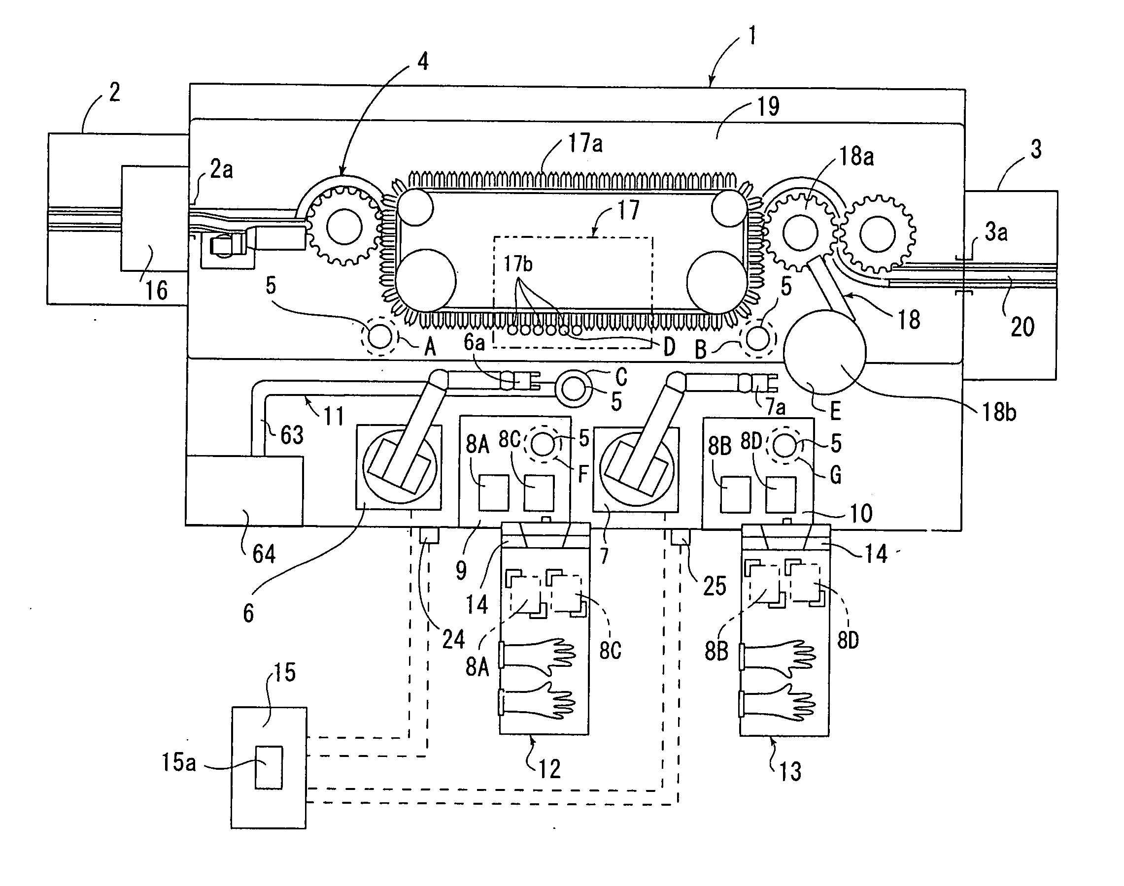
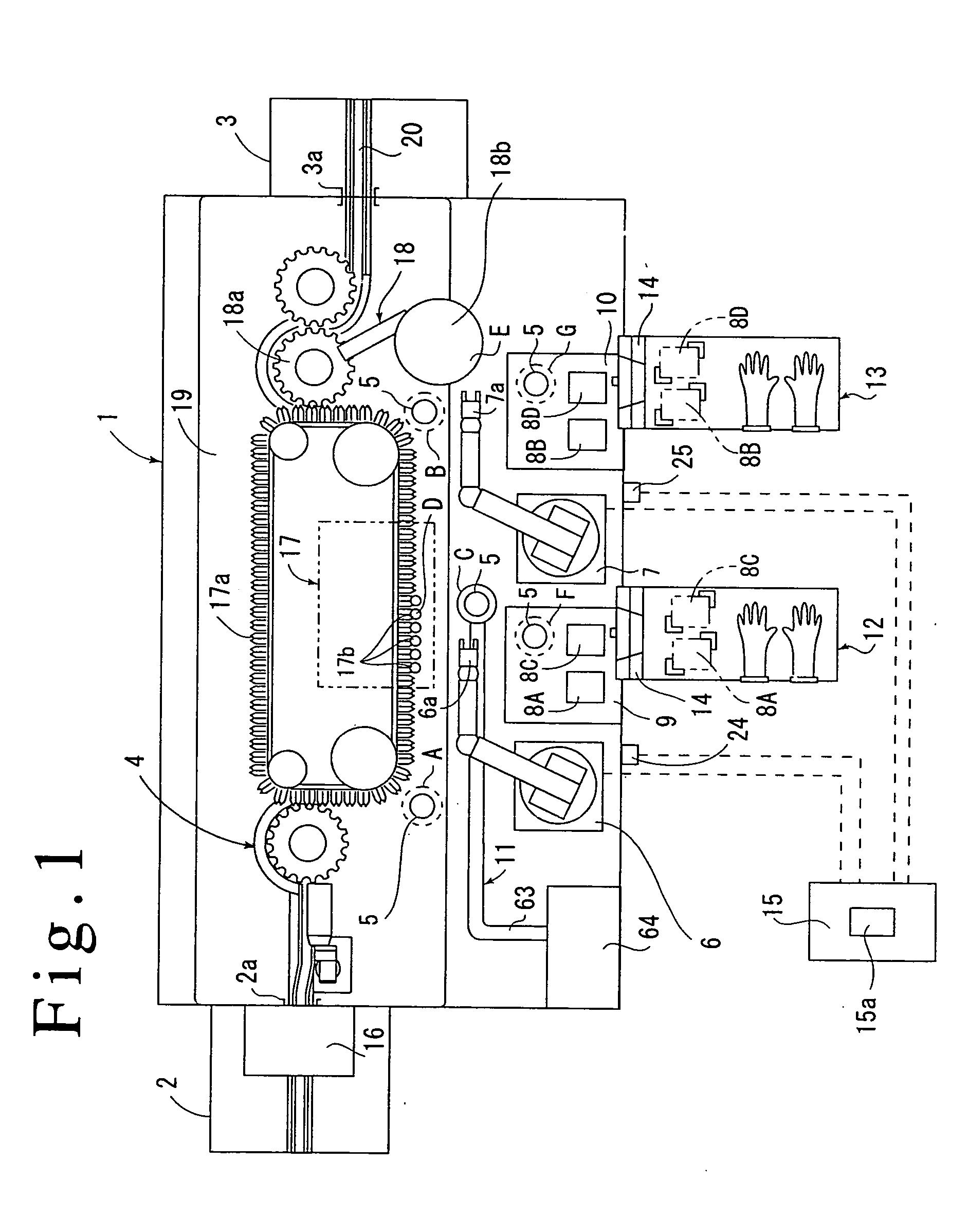
[0040] An illustrated example will be discussed below. FIG. 1 shows that a first isolator 1 is provided as a main working chamber and a filling system 4 for chemicals is provided as an article processor inside second and third isolators 2 and 3, which are provided on both sides of the first isolator 1.

[0041] Further, in the first isolator 1, first and second robots 6 and 7 are provided as handling means which hold sampling apparatus 5 for sampling microorganisms, first and second placing tables 9 and 10 are provided for placing housing racks 8A to 8D for housing the plurality of sampling apparatus 5, and a floating bacteria sampling device 11 is provided for sampling floating microorganisms.

[0042] Moreover, below the illustrated first isolator 1, fourth and fifth isolators 12 and 13 serving as sub working chambers are provided so as to be separated by connecting means 14.

[0043] Then, the first and second robots 6 and 7 and so on are controlled by a control unit 15. The control unit ...


PUM

PropertyMeasurementUnit
currentaaaaaaaaaa
suctionaaaaaaaaaa
pressureaaaaaaaaaa

Abstract

In order to sample microorganisms in a first isolator 1 before, during, and after the operation of a filling system 4, first and second robots 6 and 7 that are provided in the first isolator 1 carry a sampling apparatus 5 to first and second sampling positions A and B to sample naturally dropping microorganisms, carry the sampling apparatus 5 to a third sampling position C to sample microorganisms floating around a filling nozzle 17b, and sample microorganisms adhering to the surfaces of the predetermined filling nozzle 17b and a cap feeder 18b at fourth and fifth sampling positions D and E, respectively. Since handling means is provided in a working chamber, it is possible to prevent an operator from causing contamination in the working chamber and sample microorganisms without any manual operations.

Description

[0001] 1. Field of the Invention[0002] The present invention relates to a microorganism sampling method and a microorganism sampling device and specifically concerns a microorganism sampling method and a microorganism sampling device whereby microorganisms in a disinfected or sterilized working chamber are sampled into a sampling apparatus.[0003] 2. Description of the Prior Art[0004] Currently, an article processor is installed in a sterilized working chamber, sterilized articles are supplied to the working chamber, and the articles are processed under axenic conditions.[0005] However, in reality, it is not possible to completely deny a probability that microorganisms are left due to insufficient sterilization of the working chamber; and bacteria and microorganisms enter the working chamber when the article processor is operated.[0006] Hence, conventionally before and after an article processor is operated, an operator wears a clean suit and enters a working chamber, or the operator...

Claims


Application Information

Patent Timeline
Patent Type & Authority Applications(United States)
IPC IPC(8): A61L2/20A61L2/24A61L2/28B25J21/00B25J21/02C12M1/26G01N1/02G01N1/22
CPCA61L2/20A61L2/24A61L2/28B25J21/005C12M37/00G01N1/2202G01N1/2226G01N2001/028C12M33/04B25J21/02B08B15/023
Inventor YOSHIDA, SHIGERUYAMAMOTO, HISASHIYONEDA, KENJIOSHIMA, YASUSUKEKOKUBO, MAMORUAKERS, JAMES E. JR.
Owner SHIBUYA IND CO LTD
Why Eureka
Try Eureka