
Autonomous built-in self-test for integrated circuits
- Summary
- Abstract
- Description
- Claims
- Application Information
AI Technical Summary
Problems solved by technology
Method used
Image



Examples
second example embodiment
[0024] Second Example Embodiment of the BIST
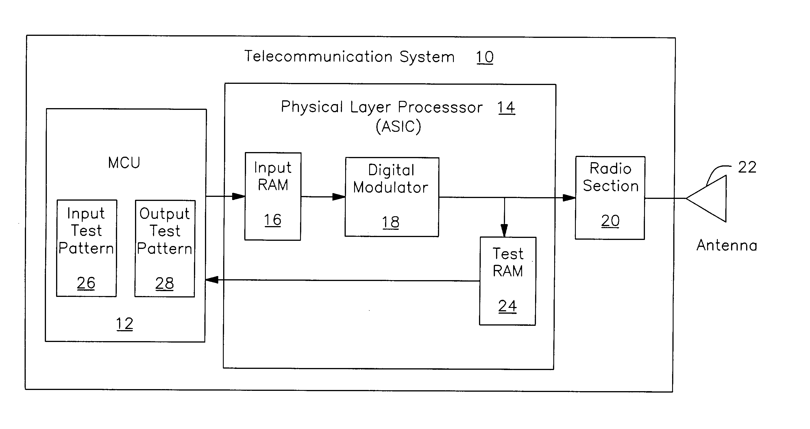
[0025] The example of FIG. 2 shows a radio system that requires much fewer resources. As with FIG. 1, the radio system 10 of FIG. 2 includes the MCU 12 connected to the physical layer processor 14 connected to the radio section 20 connected to the antenna 22. The physical layer processor connects to the MCU through an input RAM 16 and a digital modulator 18. As in FIG. 1, the MCU includes a test pattern memory 26 with one or more input test patterns and an output reference buffer 38 with a corresponding set of reference values for test output sequences. However, the reference values are different from those of FIG. 1, as described in more detail below.
[0026] In the example of FIG. 1, both the test RAM 24 and the output test pattern memory 28 may be required to be very large. If, for example, the transmit rate is 18 Megasamples per second, the transmitted samples are 10 bits wide and a transmit burst is 545 microseconds long, then the outpu...
third example embodiment
[0035] Third Example Embodiment of the BIST
[0036] FIG. 4 shows an alternative configuration for the BIST architecture of the present invention. In FIG. 4, almost all of the BIST functions are contained within the physical layer processor 14, thereby freeing MCU resources for other functions and process. In FIG. 4, the radio system 10 includes an MCU 12, physical layer processor 14, such as an ASIC and a radio section 20 coupled to an antenna 22. The ASIC includes an input RAM 16 for the bit stream that is to be transmitted and a digital modulator 18 to perform the baseband processing needed for the radio section to send the signal.
[0037] The MCU, in addition to its connection to the input RAM, communicates with the ASIC through a STARTTEST line and a SUCCESS / FAIL flag line. These can be the same or two different lines and can be multiplexed with other control lines if desired. In alternative architectures, the STARTTEST and SUCCESS / FAIL signals can be coupled to some other component...
PUM
 Abstract
Description
Claims
Application Information