

Spiral separation membrane element
Inactive Publication Date: 2004-10-07
NITTO DENKO CORP
View PDF2 Cites 22 Cited by
- Summary
- Abstract
- Description
- Claims
- Application Information
AI Technical Summary
Benefits of technology
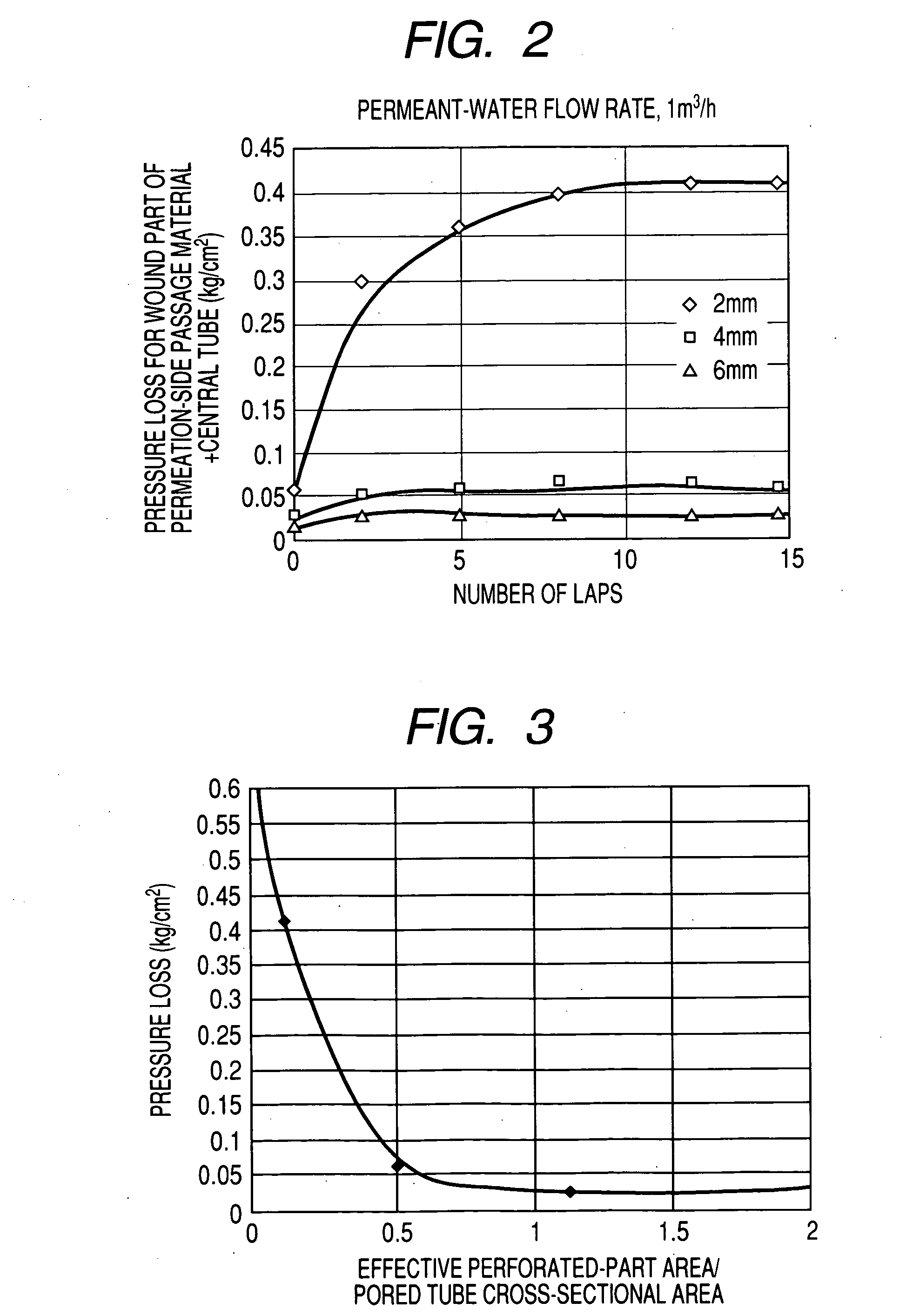
[0011] According to the present invention, since the effective perforated-part area is at least 1.0 time the cross-sectional area of the core tube, the pressure loss around the perforated parts is close to its lower limit even when the number of laps of the permeation-side passage material is 2 or larger. Because of this, the pressure loss around core tube perforated parts which is problematic especially in low pressure operations can be diminished.
[0012] In the separation membrane element described above, the permeation-side passage material interposed at the periphery of the core tube has preferably been wound so as to make substantially 2-15 laps. In this constitution, not only the passage through which the permeant liquid from each membrane leaf flows along the permeation-side passage material surrounding the cored tube has a moderately large area, but also the decrease in membrane area which is caused by too large a number of laps can be diminished. In addition, the effect of diminishing the pressure loss around core tube perforated parts, which is produced by the invention, can be sufficiently obtained.
[0013] The separation membranes preferably are ultralow-pressure reverse osmosis membranes, ultrafiltration membranes, or microfiltration membranes. Since such separation membranes are operated at low pressure, they have encountered the problem of pressure loss around core tube perforated parts as stated above. However, the present invention, which produces the effect described above, is especially effective for such separation membranes.
Problems solved by technology
However, with the recent trends toward reduction in operating pressure and increase in permeated water flow rate, that pressure loss is coming to be not negligible.
Especially in ultralow-pressure RO (reverse osmosis) membranes, which are operated at a low pressure, and in spiral separation membrane elements for clarification, influences of the pressure loss pose a serious problem.
Virtually, however, to increase the percentage of openings of a permeation-side passage material arouses a problem that the permeation-side passage material cannot retain its shape when wound around a core tube.
There are hence limitations on increasing the percentage of openings.
Furthermore, when a permeation-side passage material is wound so as to make about one lap, the area of the passage through which the permeated liquid from each membrane leaf flows along the permeation-side passage material surrounding the cored tube is small, resulting in an increased loss in this part.
This technique also is hence impractical for low-pressure operations.
Since such separation membranes are operated at low pressure, they have encountered the problem of pressure loss around core tube perforated parts as stated above.
Method used
View moreImage
Smart ImageViewing Examples

Examples
example 1
[0044] A perforated core tube was used which had an outer diameter of 22 mm, inner diameter of 16 mm, perforation diameter of 6 mm, and perforation number of 40. A polyester net having a percentage of openings of 20% and a passage material thickness of 0.29 mm was wound around the core tube to make 8 laps. (The effective perforated-part area was 1.1 times the inner cross-sectional area of the core tube.) This core tube was set in a vessel to be used in a spiral separation membrane element, and the pressure difference (pressure loss) between the outlet of the core tube in the vessel and the inlet tube was measured while changing the permeated water flow rate. The results obtained are shown in FIG. 4.
Login to View More PUM
 Abstract
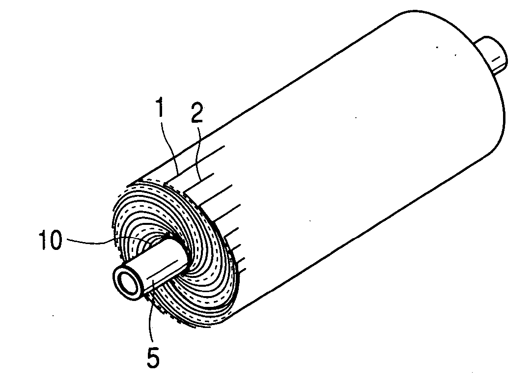
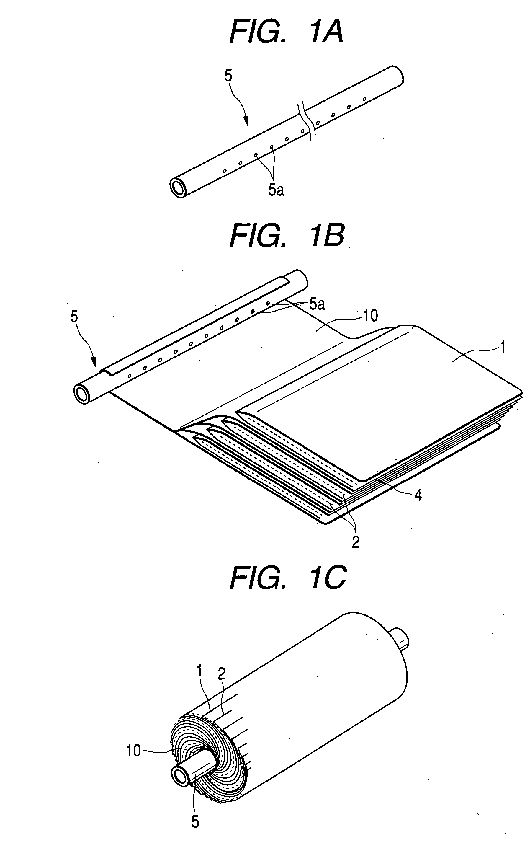
A spiral separation membrane element effective in reducing the pressure loss around core tube perforated parts, which is problematic especially in low-pressure operations. The spiral separation membrane element comprises a perforated cored tube 5 and, spirally wound therearound, separation membranes 1, feed-side passage materials 2, and permeation-side passage materials 4, the separation membranes 1 and the passage materials 2 and 4 being wound around the cored tube 5 so that the feed-side passage materials 2 and the permeation-side passage materials 4 are disposed respectively on the feed side and permeation side of the separation membranes 1 and that a permeation-side passage material 10 which is the same as or different from the permeation-side passage materials 4 is interposed at the periphery of the perforated cored tube 5, wherein the effective perforated-part area as calculated by multiplying the total area of the perforated parts in the core tube 5 by the percentage of openings of one layer of the permeation-side passage material surrounding the core tube 5 is at least 1.0 time the inner cross-sectional area of the core tube 5.
Description
[0001] The present invention relates to a spiral separation membrane element for separating ingredients suspended or dissolved in liquids. More particularly, the invention relates to a spiral separation membrane element effective in membrane separation conducted at low pressure, such as ultralow-pressure reverse osmosis filtration, ultrafiltration, or microfiltration.DESCRIPTION OF THE RELATED ART[0002] Spiral separation membrane elements have generally had a structure obtained by spirally winding one or more membrane leaves each comprising a separation membrane and a permeation-side passage material or feed-side passage material disposed thereon around a perforated cored tube while interposing a feed-side passage material or permeation-side passage material. There is a technique in which when membrane leaves are to be wound, a permeation-side passage material which is the same as or different from the permeation-side passage materials of the membrane leaves is wound around a cored ...
Claims
Login to View More Application Information
Patent Timeline
 IPC IPC(8): B01D61/08B01D61/18B01D63/10B01D67/00B01D69/10
CPCB01D63/10B01D63/107B01D63/101B01D61/025B01D61/145B01D61/147B01D2313/08
InventorHIROKAWA, MITSUAKIANDO, MASAAKICHIKURA, SHINICHIISHIHARA, SATORU
OwnerNITTO DENKO CORP