Protection device for a jet engine air intake structure

Active Publication Date: 2004-10-07
AIRBUS OPERATIONS (SAS)
View PDF31 Cites 24 Cited by
  • Summary
  • Abstract
  • Description
  • Claims
  • Application Information

AI Technical Summary

Benefits of technology

0023] The simplicity of these operations to install the device according to the invention is an another advantage, apart from the fact that the operator responsible for closing off the ventilation scoop is no longer obliged to lie down on the engine air intake structure, but on the contrary can control everything from a stable and safe position on the elevating platform. Risks of accidents related to this operator falling are therefore much reduced, and the risks of damaging the outside surface of the engine air intake structure by scratching it are also reduced.
0024] Furthermore, the fact that the protection means used to close off the ventilation scoop are fixed to the means used to close off the fan case ducting intake, introduce significant advantages compared with embodiments suggested in prior art.
0025] Firstly, it is noted that the ventilation scoop is directly released when the protective tarpaulin is removed from the engine. Consequently, the risks of forgetting to remove the protective tarpaulin from this scoop are almost entirely eliminated, since the presence of this protective tarpaulin depends entirely on the presence of the protection of the fan case ducting intake, which is clearly visible to operators located on the ground.
0026] Furthermore,

Problems solved by technology

Obviously, this introduces serious safety problems for the operator performing this task, and risks of this operator falling are high due to the very uncomfortable position.
Moreover, the risks arising as a result of this assembly may strongly discourage operators from performing the task.
Consequently, if the ventilation scoop 20 is not closed off before a long term storage phase of the aircraft, particularly dangerous situations can arise in which harmful elements have actually entered the ventilation duct.
Another disadvantage due to the presence of such a cap 22 is due to the fact that when it is assembled on the ventilation scoop 20, this cap 22

Method used


Image

  • Protection device for a jet engine air intake structure
  • Protection device for a jet engine air intake structure
  • Protection device for a jet engine air intake structure

Examples


Embodiment Construction

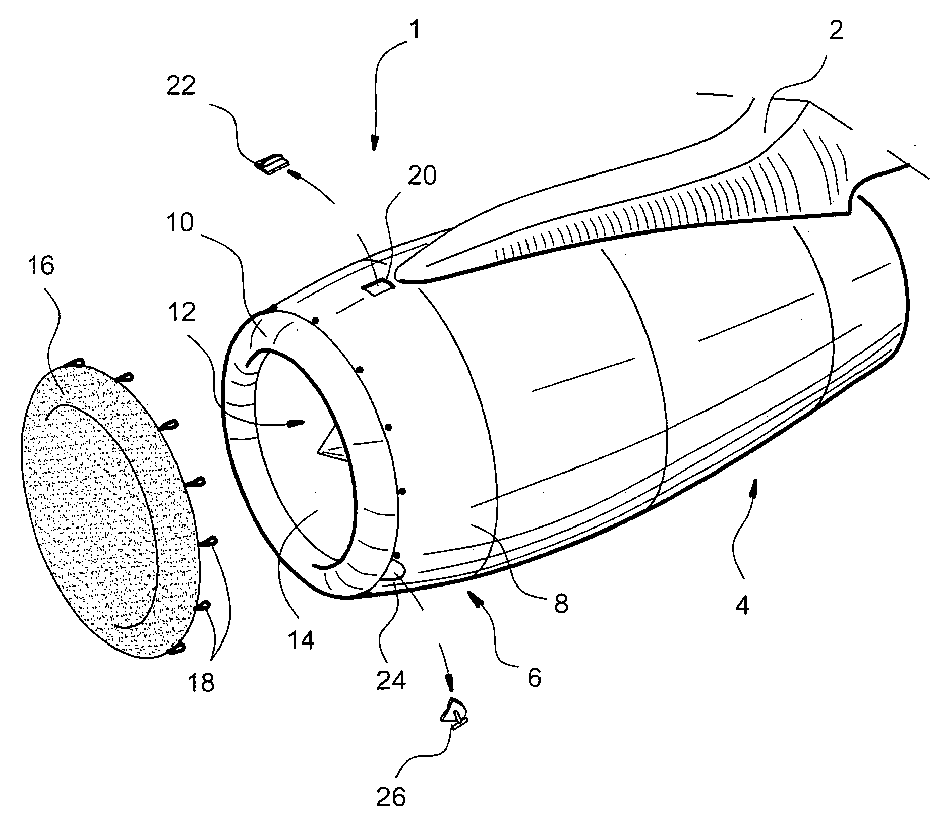
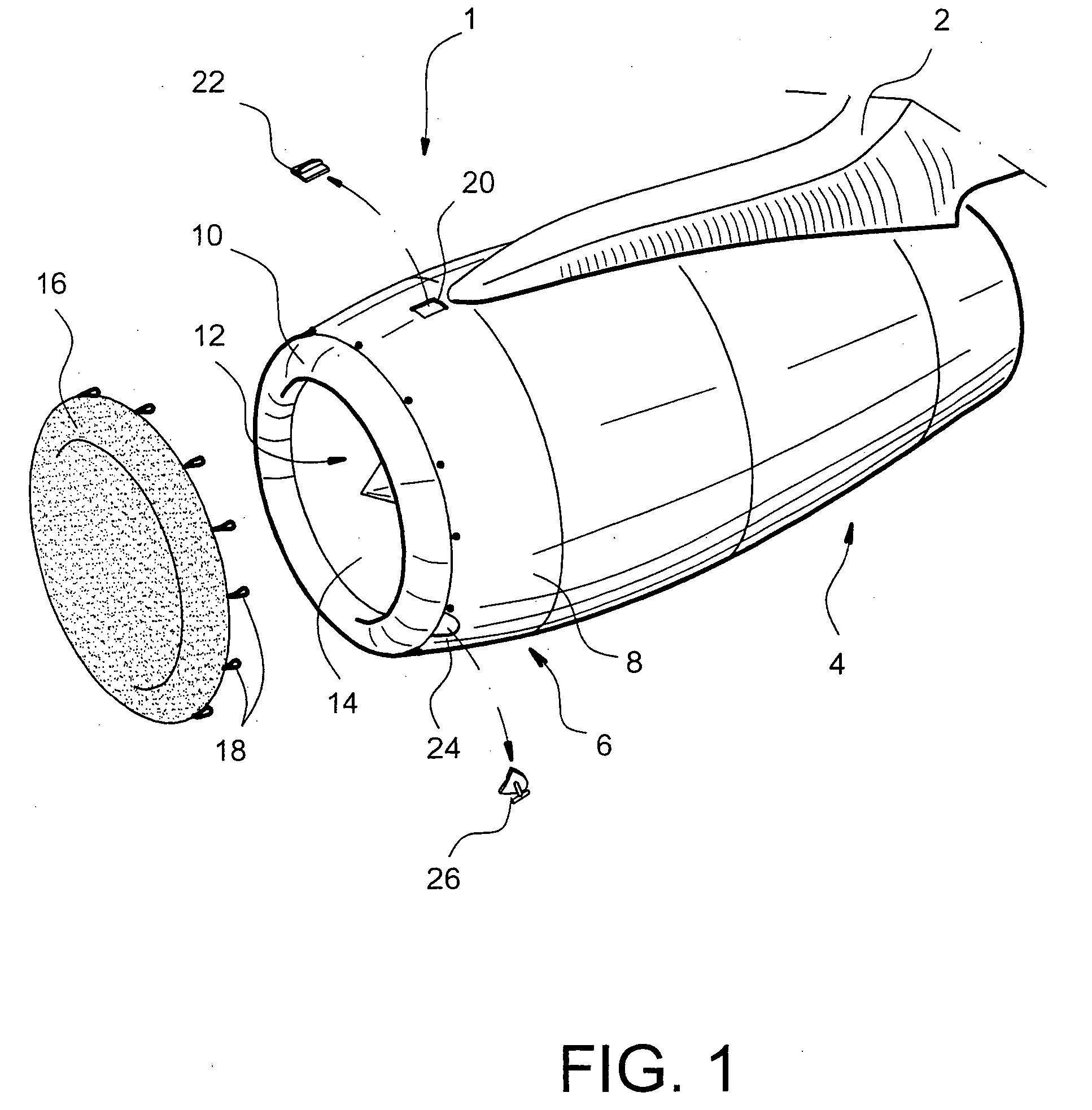
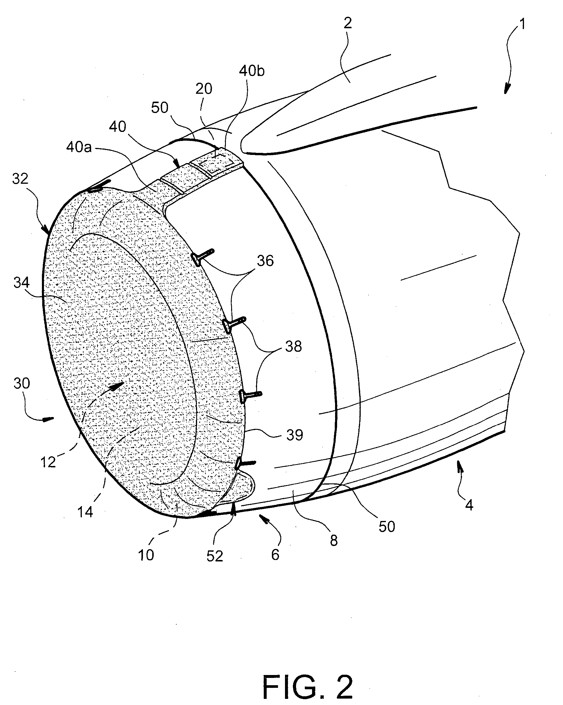
[0043] FIG. 2 shows an air intake structure 6 for a conventional jet engine 1, designed to be installed on an aircraft (not shown) through a mast 2 fixed to a nacelle 4 of the engine, the engine being practically the same as that shown in FIG. 1 described above.

[0044] Consequently, it can be seen in this FIG. 2 that elements with the same numeric references as the references attached to elements shown in FIG. 1, correspond to identical or similar elements.

[0045] Thus, the air intake structure 6 located at the front of the nacelle 4 is composed of an air intake cowl 8 provided with a ventilation scoop 20 on its top portion, this scoop 20 forming part of a ventilation duct (not shown). It is noted that the ventilation scoop 20 is usually located at the top part of the air intake cowl 8, approximately along the line of the mast 2.

[0046] Furthermore, the cowl 8 also comprises one or several exhaust orifices (not shown in FIG. 2) forming part of a hot air duct (not shown), these exhaust ...


PUM


Abstract

This invention relates to a protection device (30) for an air intake structure (6) of a jet engine (1), said structure comprising an air intake cowl (8) and an air intake lip (10) that jointly delimit a fan case ducting (12), the cowl having a top portion provided with at least one ventilation scoop (20) and the lip defining a fan case ducting intake (14), the device comprising a protective tarpaulin (32) with a main portion (34) designed to close off the intake (14) when the device is assembled on the structure (6). According to the invention, the protective tarpaulin also comprises a secondary portion (40) fixed to the main portion, said secondary portion being provided with stiffening means (42) and designed to partially cover the cowl (8), to close off each ventilation scoop.

Description

TECHNICAL DOMAIN[0001] This invention relates generally to the domain of protection for a jet engine air intake structure installed on an aircraft. This protection is intended particularly to be assembled on the engine during long term aircraft storage phases, in order to prevent access inside the engine.STATE OF PRIOR ART[0002] FIG. 1 shows a conventional jet engine 1 designed to be installed on an aircraft (not shown) wing, through a mast 2 fixed to a nacelle 4 for this jet engine.[0003] The front part of the nacelle 4 includes an air intake structure 6 composed of an air intake cowl 8, prolonged by an air intake lip 10. Note that the cowl 8 and the lip 10 jointly delimit the outside of an annular fan case ducting 12, for which an intake 14 is defined by the lip 10.[0004] Thus, during long term aircraft storage phases, for example during the night, this intake 14 to the fan case ducting 12 needs to be closed off to prevent the entry of objects into the engine 1.[0005] To achieve t...

Claims


Application Information

Patent Timeline
IPC IPC(8): B64F1/00F02C7/04
CPCB64F1/005Y02T50/671F02C7/04Y02T50/60
Inventor GARRIC, STEPHANE
Owner AIRBUS OPERATIONS (SAS)
Why Eureka
Try Eureka