Infrared endoscopic balloon probes

a balloon probe and infrared technology, applied in the field of probes, can solve the problems of increasing the risk of complications for patients, limited ability of conventional endoscopes, and inability to detect all pathology or provide unequivocal, and devices that do not combine balloon endoscopes with infrared radiation to detect diseased tissu

Inactive Publication Date: 2004-10-14
HYPERSPECTRAL IMAGING
View PDF8 Cites 138 Cited by
  • Summary
  • Abstract
  • Description
  • Claims
  • Application Information

AI Technical Summary

Problems solved by technology

However, conventional endoscopes, such as colonoscopes, gastroscopes, bronchoscopes, and angioscopes, are limited in their ability to detect all pathology present or provide unequivocal identification of abnormalities.
Unfortunately, the biopsy process increases the risk of complications to the patient, such as hemorrhage, infection, and possible perforation of the organ or vessel under examination.
This device does not incorporate balloons into the probes to facilitate optical coupling, to allow infrared-based evaluation of the diseased tissue.
However, these devices do not combine balloon endoscopes with infrared radiation to detect diseased tissue.
However, prior to the present invention, these conventional balloon devices could not be used in procedures in which infrared light is emitted in close proximity or directly onto a tissue surface, followed by collection of the light reflected or emitted from the tissue of interest, due to moisture and fluids in the surrounding environment.
The use of infrared radiation in catheters and endoscopic devices is complicated by the fact that water and most bodily fluids are opaque to infrared light.
Consequently, even the slightest amount of moisture on the collection end of an endoscopic probe impairs the collection of infrared light.
As a result, conventional endoscopes and balloon catheters cannot be used in infrared procedures where moisture or bodily fluids are present.
As can be seen, because of the challenges posed by the effect of moisture on infrared light transmission, available endoscopic devices and catheters are limited in their ability to access and evaluate tissue and / or the lumen of vessels and organs using infrared light.

Method used


Image

  • Infrared endoscopic balloon probes
  • Infrared endoscopic balloon probes

Examples


second embodiment

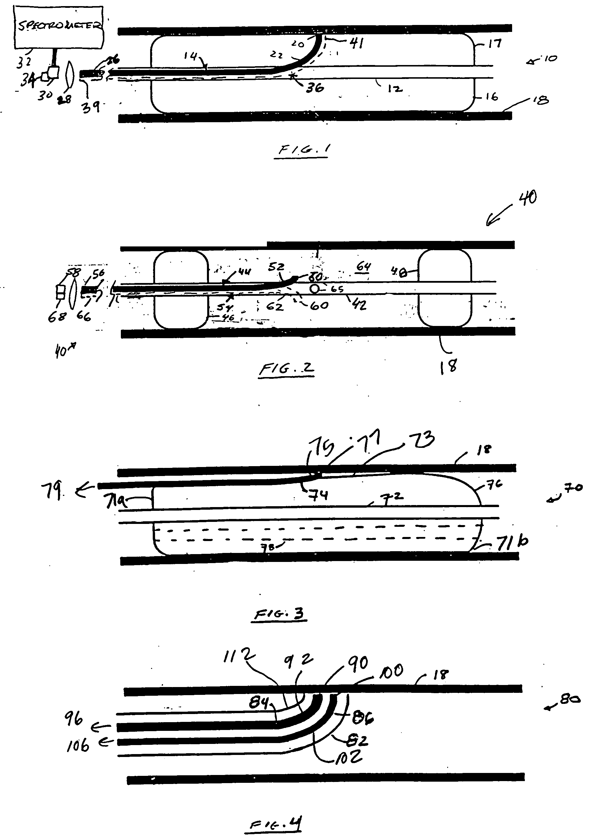
[0051] FIG. 2 depicts the present invention. Referring to FIG. 2, second probe device or probe 40 includes sheath 42, optical fiber 44, proximate balloon 46 and distal balloon 48. Optical fiber 44 includes distal optical collection end 50, proximal optical end 56, and bend 52 disposed proximate to collection end 50. Probe 40 may differ from probe 10 in that the collection end 50 is not in apposition with or disposed inside the balloon, but instead sits between the distal and proximate balloons. The collection ends of probe 40 may or may not be in apposition with tissue surface 18. Sheath or conduit 42 also includes opening 65 which connects or allows communication between the inside of sheath 42 with volume 64. Volume 64 is defined by proximate balloon 46, distal balloon 48, and tissue surface 18. Proximal optical end 56 of fiber 44 is functionally coupled to detector 58, such as a detector array, via a spectrometer.

first embodiment

[0052] Probe 40, like probe 10 of the first embodiment, may be implemented as a single-fiber or multi-fiber probe by providing one or more additional fibers 54 that run next to first fiber 44 in a bundle. Fibers 54 may each include a bend 62 in a different plane causing fibers 54 to diverge radially from first fiber 44 and from each other. Alternately, the fibers may have axially offset bends 62 in the same plane. Each of the fibers 54 has a distal collecting end 60 and a proximate end 66, which may be coupled to an additional detector 68 via a spectrometer. The first detector 58 and the additional detector(s) 68 may form part of a detector array, such as a focal plane array (FPA). Alternately, the multiple fibers in this embodiment may be serviced by a single detector and an optical multiplexer.

[0053] In operation, probe 40 is positioned in the area of interest, and distal and proximate balloons 46 and 48 are inflated. This creates cavity or enclosed volume 64 between the two ballo...

third embodiment

[0054] FIG. 3 depicts the present invention. Referring to FIG. 3, probe or probe device 70 includes sheath 72, balloon 76 and fiber 74. Fiber 74 has a distal collection end 77 and a proximal end 79. In this embodiment, the fiber or fibers may be, but need not be, fixed to an outer surface 73 of balloon 76. Probe 70 may further include a bend 75, or a reflector that redirects light from collection end 77 into the fiber 74. The fiber or fibers may be introduced separately from the balloon using a guidewire. Apposition to the wall may be accomplished by simple inflation of balloon 76.

[0055] Although probes 10, 40 and 70 are occlusive, probes 10 and 70 may employ an autoperfusion balloon to allow antegrade blood flow during inflation. The balloon may be toroidally shaped. The balloon may have a passage 78 that is either centrally located or offset from the center. For example, as depicted in FIG. 3, passage 78 allows fluid communication between proximate end 71a and distal end 71b of ba...


PUM


Abstract

Balloon probes, adapted for use in endoscopy and other medical procedures, are useful to obtain spectroscopic information reflected or emitted from a tissue of interest in the infrared spectral region. The information collected by the probe is useful in the diagnosis and treatment of disease. The invention also relates to methods utilizing these probes to analyze a surface of interest, in a minimally invasive manner, in connection with the diagnosis and treatment of disease.

Description

[0001] This application claims the benefit of U.S. Provisional Patent Application Serial No. 60 / 098,957 filed Sep. 3, 1998.[0003] 1. Field of the Invention[0004] The present invention relates to probes useful in endoscopy and other procedures, and more particularly to balloon probes adapted to obtain spectroscopic information in the infrared spectral region. The invention also relates to methods that utilize these probes to analyze a surface of interest in connection with the diagnosis and treatment of disease.[0005] 2. Description of the Background[0006] Numerous minimally-invasive diagnostic and treatment devices and methods of using them have been developed. Two such categories of devices are endoscopes and balloon catheters.[0007] Endoscopes have proved useful in the examination of internal surfaces, in connection with various surgical and diagnostic procedures. However, conventional endoscopes, such as colonoscopes, gastroscopes, bronchoscopes, and angioscopes, are limited in t...

Claims


Application Information

Patent Timeline
Patent Type & Authority Applications(United States)
IPC IPC(8): A61B5/00
CPCA61B5/0075A61B5/0086A61B5/6853A61B5/6885A61B1/00009A61B1/00082A61B1/00135A61B1/04A61B1/07A61B1/046
Inventor FREEMAN, JENNY E.LAMBERT, CHARLES R.HOPMEIER, MICHAEL I.
Owner HYPERSPECTRAL IMAGING
Why Eureka
Try Eureka