
Evaporation chamber for a loop heat pipe

a loop heat pipe and evaporation chamber technology, applied in the direction of insulated conductors, semiconductor/solid-state device details, cables, etc., can solve the problem of diminishing the dimensions of the evaporating chamber, and achieve the effect of reducing parasitic heat leakage, increasing heat load, and improving device efficiency

Inactive Publication Date: 2004-10-21
MICROWAY
View PDF0 Cites 59 Cited by
  • Summary
  • Abstract
  • Description
  • Claims
  • Application Information

AI Technical Summary

Benefits of technology

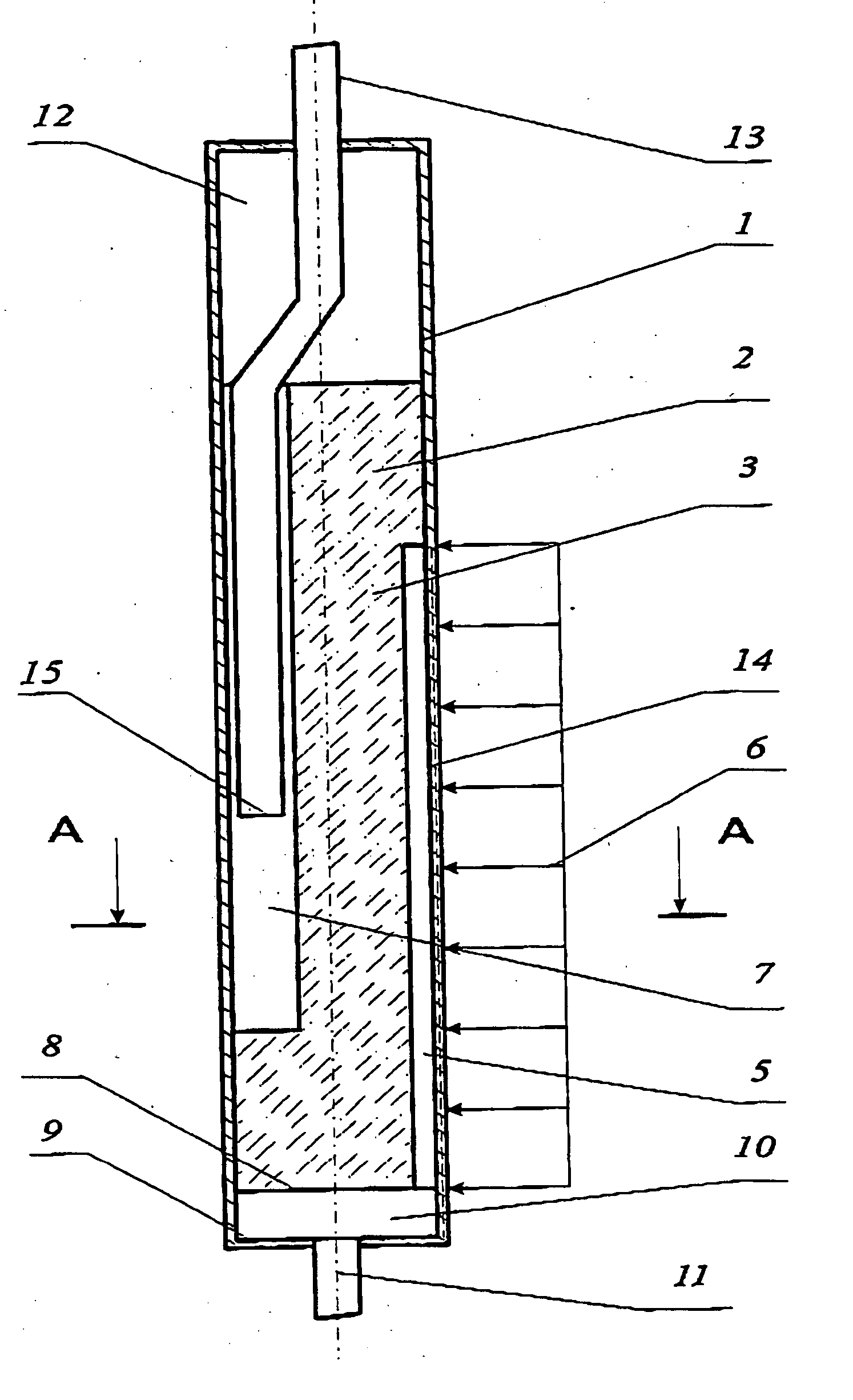
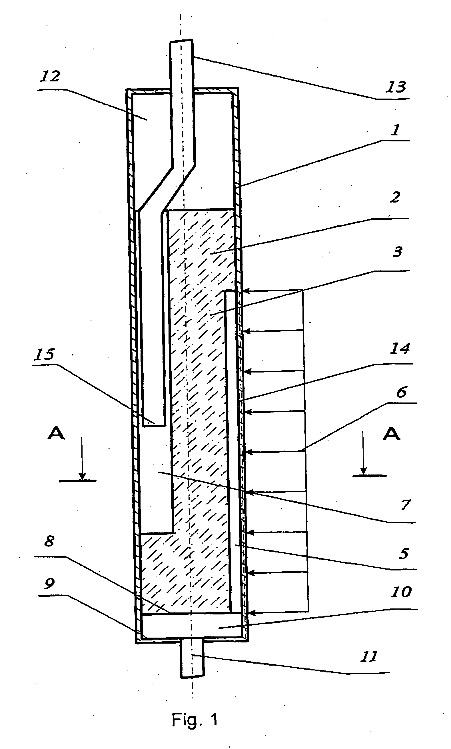
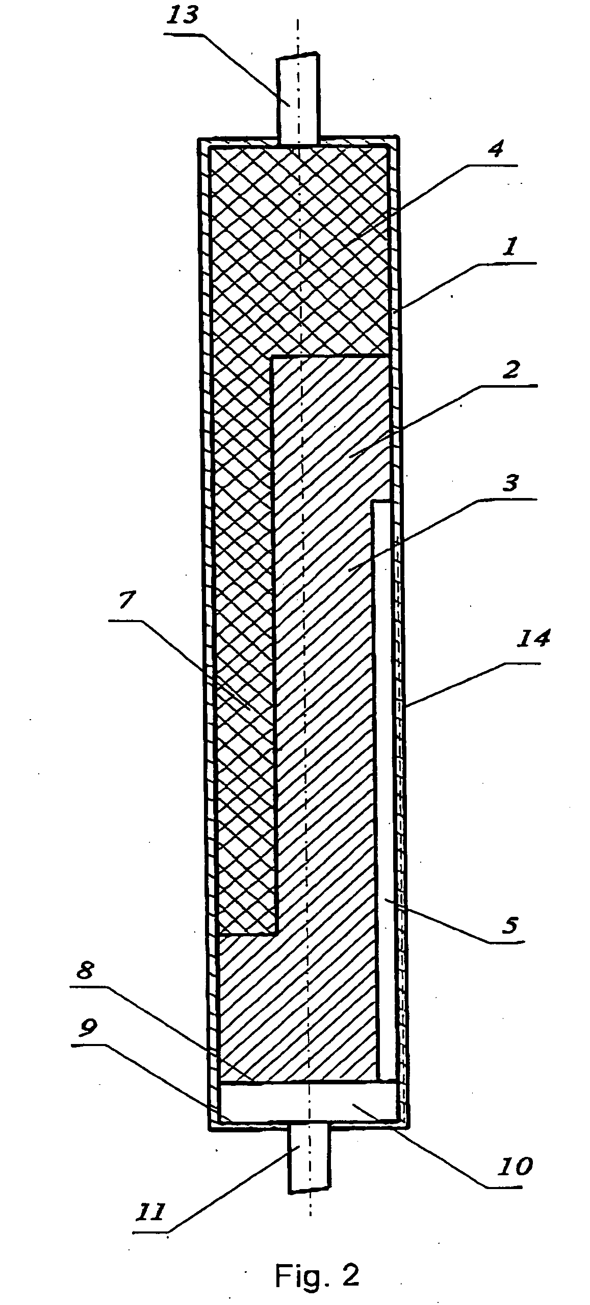
[0011] Owing to the fact that the asymmetrical longitudinal opening in the capillary porous packing is blind, the device efficiency is improved as there is a decrease in parasitic heat leakages into the compensation cavity, which results in an increased heat load at a given operating temperature. Further, dimensions of the evaporating chamber diminish as this a design requires only one end-face locking layer of a capillary porous packing. This result in a decrease in the longitudinal dimension of the evaporating chamber, and the proposed arrangement of the vapor collector and the vapor-removal channels allows to connect the vapor line of a loop heat pipe to the end-face wall, which results in decreasing the transverse dimension and increasing possibilities to carry out a compact assembly in a miniature cooled object.
[0012] Besides, to improve the heat exchange efficiency and decrease the thermal resistance of a device, additional vapor-removal grooves may be made on the inner surface of the side wall of the body, for instance, in the form of azimuthal grooves.
[0014] Disposition of the condensate-line outlet in the asymmetrical longitudinal opening of the capillary porous packing ensures its replenishment with a heat-transfer medium, even if in the compensation cavity there is a vapor phase, which may impede passage of a working fluid through the asymmetrical longitudinal opening.

Problems solved by technology

Further, dimensions of the evaporating chamber diminish as this a design requires only one end-face locking layer of a capillary porous packing.

Method used


Image

  • Evaporation chamber for a loop heat pipe
  • Evaporation chamber for a loop heat pipe
  • Evaporation chamber for a loop heat pipe

Examples


Embodiment Construction

[0018] A form and the disposition of the replenishment asymmetrical channel may vary depending on required conditions for cooling a miniature heat-releasing object. Versions of the evaporating chamber, in which versions cross-section of the asymmetrical longitudinal opening has the form of a rectangle elongated in the direction of heat supply and limited on the opposite side by a body wall (FIG. 3), or the form of a wedge whose apex is directed to heat supply and whose base is a body wall (FIG. 4), ensure a sufficiently high heat load of the evaporating chamber. The form of a wedge is more preferable in the case that the heat load is distributed along a greater part of perimeter as such design ensures a higher thermal resistance to parasitic heat leakages into the compensation cavity.

[0019] To reduce the start-up heat load, cross-section of the asymmetrical longitudinal opening may have the form of a segment whose chord is directed towards heat supply, and the arc is a body wall (FI...


PUM


Abstract

The invention relates to heat engineering, in particular to heat pipes, and may be used for heat removal from miniature heat-tensioned objects, in particular elements of radioelectronic devices and computers requiring effective heat removal within minimum dimensions of a cooling system. The invention is aimed at increasing a heat load of the evaporating chamber at a given operating temperature and reducing its dimensions. For this purpose, in the evaporating chamber of a loop heat pipe comprising a body that includes side and end-face walls and a capillary porous packing accommodated in said body and having vapor-removal channels tied together by a vapor collector, and disposed on a portion of the packing perimeter at the heat-supply side, and having an asymmetrical longitudinal opening shifted in the direction opposite to the heat supply, the end-faces of the vapor-removal channels being blind at one side, the asymmetrical longitudinal opening is also being blind at the side opposite to the blind end-faces of the vapor-removal channels, and the vapor collector is formed by one of the end-face walls of the body and the packing end-face. Besides, on the inner side surface of the body, additional vapor-removal grooves are provided. Cross-section of the asymmetrical longitudinal opening may have the form of a rectangle elongated in the direction of the heat supply and limited at the opposite side by a body wall, or the form of a wedge, whose apex faces the heat supply and whose base is a body wall, or the form of a segment, whose chord is directed towards the heat supply and the arc is a body wall, or the form of a circle limited by a capillary porous packing and whose center is shifted in the direction opposite to the heat supply. Cross-section of the evaporating chamber may be made rectangular, the asymmetrical longitudinal opening, which has the form of a slot gap being shifted in the direction opposite to the heat supply. The capillary porous packing may consist of two interconnected parts. The outlet of the condensate line is positioned in the asymmetrical longitudinal opening of the capillary porous packing.

Description

[0001] The invention relates to heat engineering, in particular to heat pipes, and may be used for heat removal from miniature heat-dense objects, in particular elements of radioelectronic devices and computers requiring effective heat removal within at minimum dimensions of a cooling system.BACKGROUND OF INVENTION[0002] Known is a reversible heat-transfer device [1] which comprises evaporating chambers consisting of a heated portion and a compensation cavity, each equipped with an internally-accommodated a capillary porous packing having a central blind channel and a system of vapor-removal channels on thermal contact surfaces that communicate with a vapor collector.[0003] The drawback of such design is the fact that the possibilities for reducing the diameter of the evaporating chamber are considerably limited as the thickness of the layer of the packing separating its absorbing and evaporating surfaces should be sufficiently large to prevent vapor penetration and decrease parasit...

Claims


Application Information

Patent Timeline
IPC IPC(8): F28D15/04
CPCF28D15/043
Inventor MAYDANIK, YURY FOLYEVICHSUDAKOV, ROMAN GRIGORYEVICHVERSHININ, SERGEY VASILYEVICH
Owner MICROWAY
Learn More