
Concussion stunner

Inactive Publication Date: 2004-10-21
JARVIS PROD
View PDF10 Cites 29 Cited by
  • Summary
  • Abstract
  • Description
  • Claims
  • Application Information

AI Technical Summary

Benefits of technology

[0020] The piston of the concussion stunner is preferably integrated into a single piece with the stunning rod and the impact head and catch end are attached thereto. This allows the piston and stunning rod to be made of a lighter material than the impact head and catch end. The stunning rod, catch end and impact head are all preferably hollow to reduce weight. Because the catch end and impact head are removable, they can be made of different materials than the stunning rod. Specifically, the catch end can be made of a more wear resistant material and the impact head can be more impact resistant.
[0022] A further aspect of the invention is that the activator is designed as an axially sliding sleeve that surrounds the stunning rod and includes one or more openings for venting air ahead of the stunning rod. This venting prevents the buildup of pressure ahead of the stunning rod, which tends to slow it and decrease the stunning energy. It also prevents air from being forced into the animal's skull by the stunning rod.
[0024] Still another aspect of the invention is the provision of an anti-friction coating on the inner surface of the cylinder. The anti-friction coating acts to increase stunning rod speed by minimizing friction between the cylinder and the piston as the piston drives the stunning rod.
[0025] An additional aspect of the invention intended to improve stunning rod speed is a low-friction pivoting latch mechanism formed as a plurality of pivoted catch fingers. The catch fingers quickly and completely release the piston as they pivot to an open position.

Problems solved by technology

However, a stunning hammer is heavy and must be swung over a relatively long stroke to achieve the required energy needed to produce concussion.
Such a tool is tiring to wield and is relatively slow.
Consequently, it is unsuitable for most modern meat processing operations.
Although penetrating rod designs have proven to be very effective, they cannot be used in slaughtering operations where civil or religious rules prohibit penetration of the animal's skull.
Even where such rules do not apply, there is a growing concern over potential disease contamination during any meat processing operation that penetrates or exposes any portion of the animal's nervous system.
These characteristics have been believed to be incompatible with modern penetrating rod designs and the requirements of high speed meat processing operations.
This would result in an objectionably bulky and heavy tool.
This size and pressure restriction limits the force that can be applied to accelerate the stunning head and the distance over which that force can be applied, thereby limiting the speed of the head according to the mass of the head.
However, this diameter increase causes several problems when attempting to decrease the mass and increase the speed of the stunning head.
One problem is that the large diameter of the head tends to increase its mass.
This has a detrimental effect on tool operation by slowing the speed of the head.
A second problem involves the extension distance of the stunning head from the tool and the high stunning energy given to the head.
Because the stunning head is not permitted to penetrate the animal, the distance it extends beyond the tool must be more limited than in a penetrating bolt design.
This can damage the tool if it occurs repeatedly.
However, adapting such an optimal actuator design to a large diameter lightweight stunning head design has proven to be unexpectedly difficult.
One difficulty relates to the air located ahead of the large diameter stunning head inside the actuator.
The light weight of the stunning head means that such a pressure buildup can have a disproportionately large effect and slow the stunning head to below the required minimum stunning energy.
Controlling the extension distance of the stunning head beyond the front of the tool is yet another difficulty found in a concussion-based design that is not found in a penetrating rod design.

Method used


Image

  • Concussion stunner
  • Concussion stunner
  • Concussion stunner

Examples


Embodiment Construction

(s)

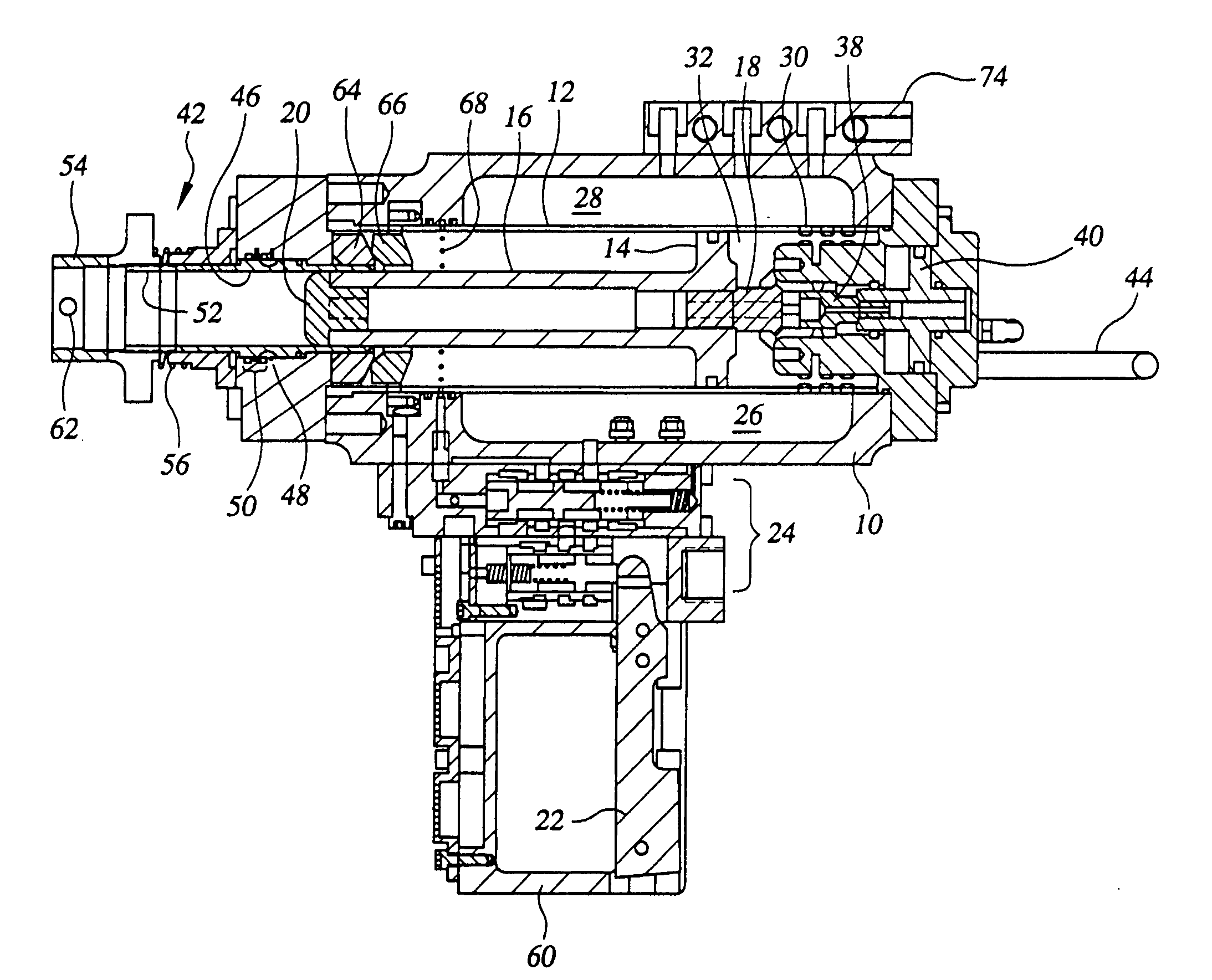
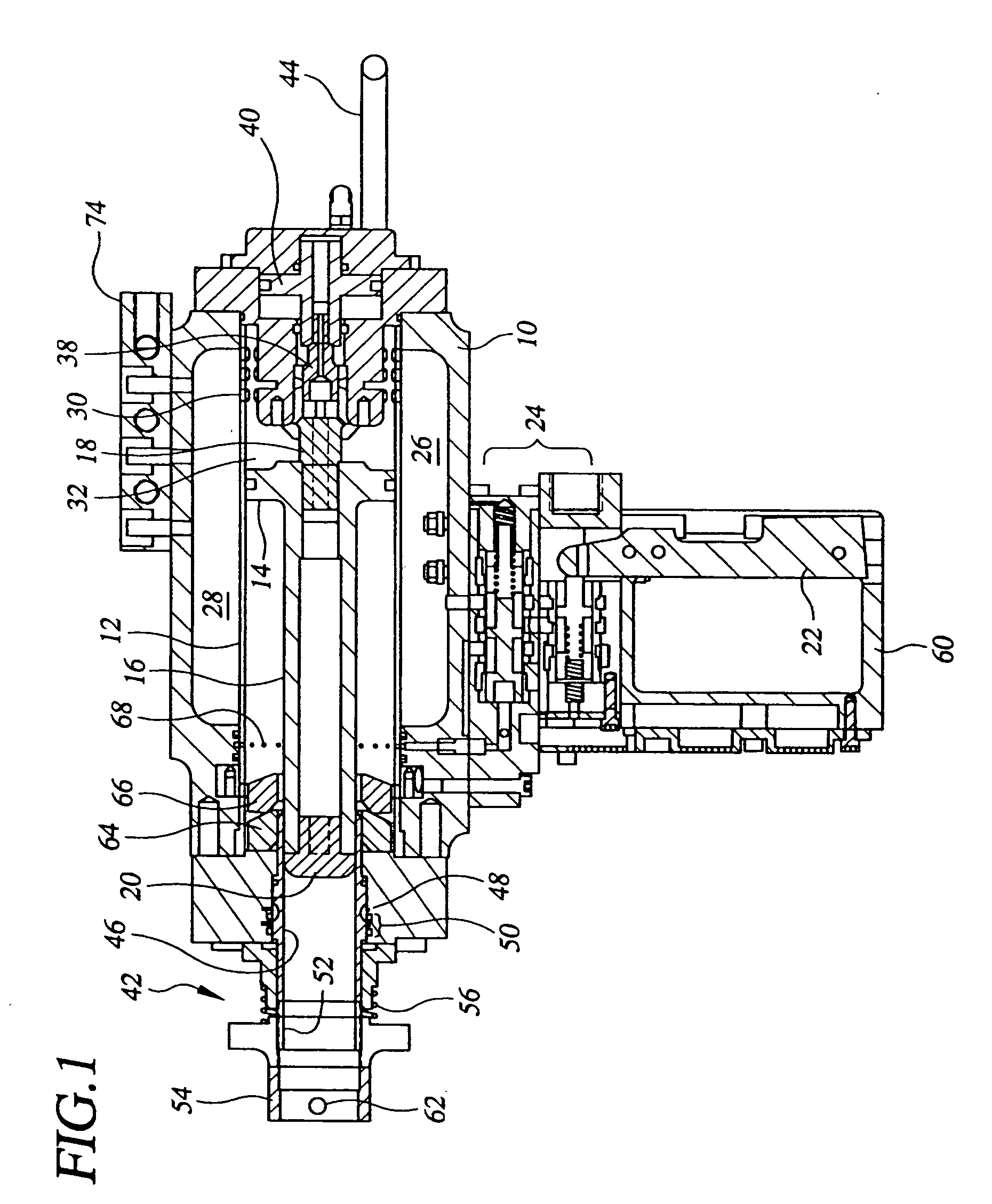
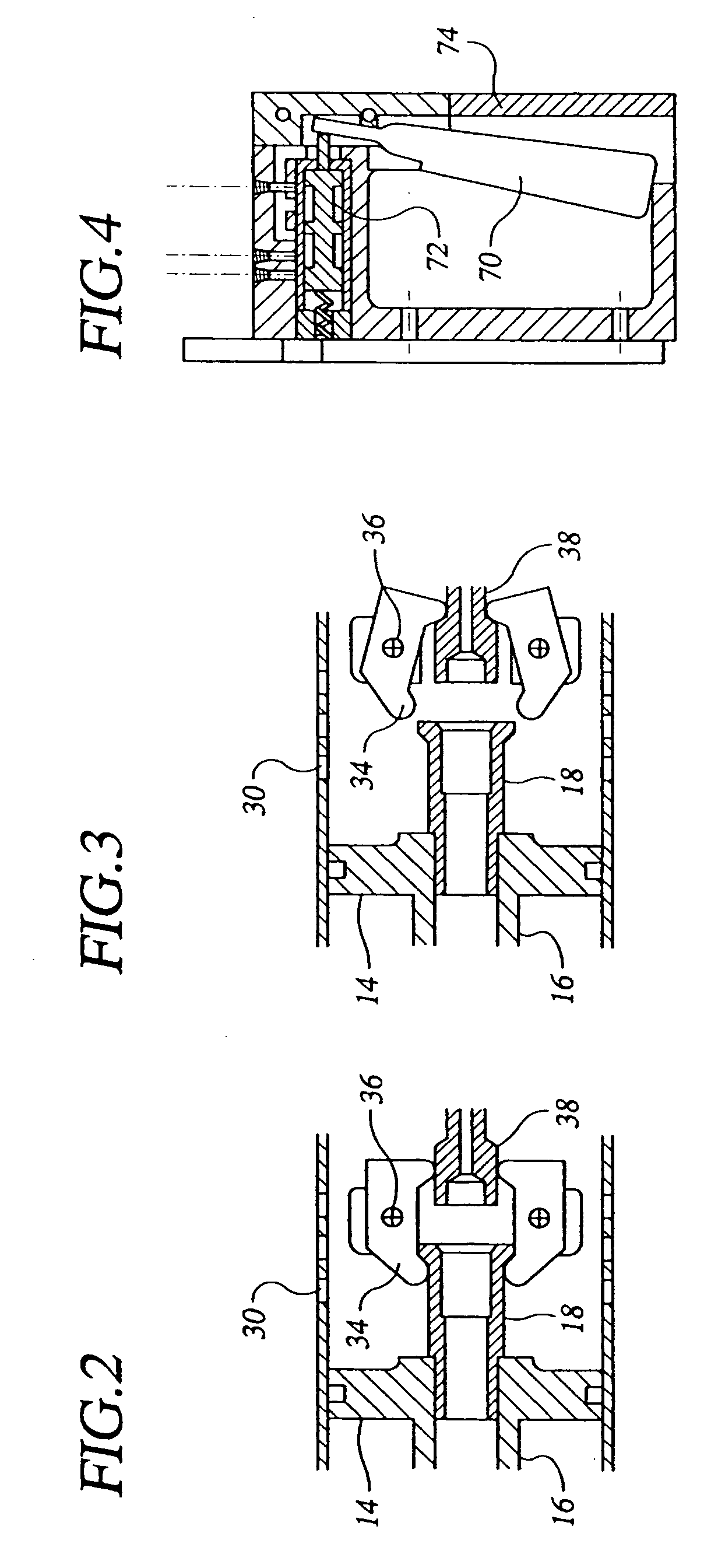
[0031] In describing the preferred embodiment of the present invention, reference will be made herein to FIGS. 14 of the drawings in which like numerals refer to like features of the invention.

[0032] Referring to FIG. 1, the concussion stunner of the present invention includes a housing 10 having a cylinder 12 located inside and a piston 14 that slide within the cylinder. The piston 14 is preferably integrally formed as part of a stunning rod 16 having a catch end 18 and an impact head 20. The integrated piston 14 and stunning rod 16 are preferably constructed of a lightweight material, such as aluminum, to minimize weight.

[0033] The catch end 18 is preferably formed of a wear-resistant material, such as steel. An impact resistant material is used for the impact head 20. Tool steel, stainless steel and similar materials are suitable for the impact head 20 and the catch end 18. If desired, the catch end and the impact head can be removed. This allows these pieces to be replaced if...


PUM


Abstract

A pneumatically operated animal stunner achieves a high stunning energy to produce concussion and stun an animal without penetration by accelerating a lightweight stunning rod to high speed. The stunning rod is preferably hollow and made of a lightweight material. A piston sliding within a cylinder with an anti-friction coating drives the stunning rod. To increase stunning rod speed, air is vented ahead of the stunning rod. One end of the stunning rod is provided with a large diameter impact head of a material that resists deformation. The opposite end is made of a wear resistant material and is engaged by the catch. The extension distance of the impact head beyond the front end of the tool is limited and can preferably be adjusted. A specially shaped air-cooled internal bumper is provided to absorb the very high stunning energy of the stunning rod without damage.

Description

[0001] 1. Field of the Invention[0002] The present invention relates to animal stunners used in meat processing operations. More specifically the present invention relates to animal stunners that stun the animal by concussion instead of penetration.[0003] 2. Description of Related Art[0004] In livestock and meat processing operations incoming animals are first disabled with a stunner. An early method of stunning used a heavy stunning hammer swung by hand. A stunning hammer achieves its effect by concussion without penetrating the skull. However, a stunning hammer is heavy and must be swung over a relatively long stroke to achieve the required energy needed to produce concussion. Such a tool is tiring to wield and is relatively slow. Consequently, it is unsuitable for most modern meat processing operations.[0005] Modern animal stunners use a penetrating rod that is pneumatically driven into the skull of the animal. Animal stunners of this type achieve the stunning effect by penetrati...

Claims


Application Information

Patent Timeline
IPC IPC(8): A22B3/02
CPCA22B3/02
Inventor JONES, ARTHUR
Owner JARVIS PROD
Learn More