Automatic optical axis direction adjusting device for vehicle headlight

Inactive Publication Date: 2004-10-21
DENSO CORP
View PDF5 Cites 8 Cited by
  • Summary
  • Abstract
  • Description
  • Claims
  • Application Information

AI Technical Summary

Benefits of technology

[0015] It is another object of the present invention to provide an automatic optical axis direction adjusting device for a vehicle headlight, which can decide necessity for an adjustment of the optical axis direction of the vehicle headlight without a brightness sensor and can avoid unnecessary operation of a driving system such as an actuator to increase durability by restricting or stopping the adjustment.
[0018] In the above automatic optical axis direction adjusting device for the vehicle headlight, the control characteristic is switched by the control characteristic switching means according to a road condition, a designation by a user or the like. Therefore, the optical axis direction of the vehicle headlight can be adjusted to suit a vehicle driving condition, a driver's preference or the like without causing a driver to feel uncomfortableness. Furthermore, the adjustment of the optical axis direction can be stopped or restricted according to the switched control characteristic. Therefore, unnecessary operation of a driving system such as an actuator can be avoided to increase durability.

Problems solved by technology

Therefore, the headlight may not be suitably adjusted when a road condition changes.
Furthermore, the adjustment may not suit for a driver's preference.
However, such an exaggerated system is unnecessary when front visibility is ensured, for example, in a road sufficiently brightened by a streetlight.
To the contrary, such a system causes a driver to feel uncomfortableness because the optical axis direction is adjusted unnecessarily.
However, it is guessed that the brightness sensor actually needs to detect brightness even outside an area where the headlight brightens a forward road.

Method used


Image

  • Automatic optical axis direction adjusting device for vehicle headlight
  • Automatic optical axis direction adjusting device for vehicle headlight
  • Automatic optical axis direction adjusting device for vehicle headlight

Examples


first embodiment

[0028] (First Embodiment)

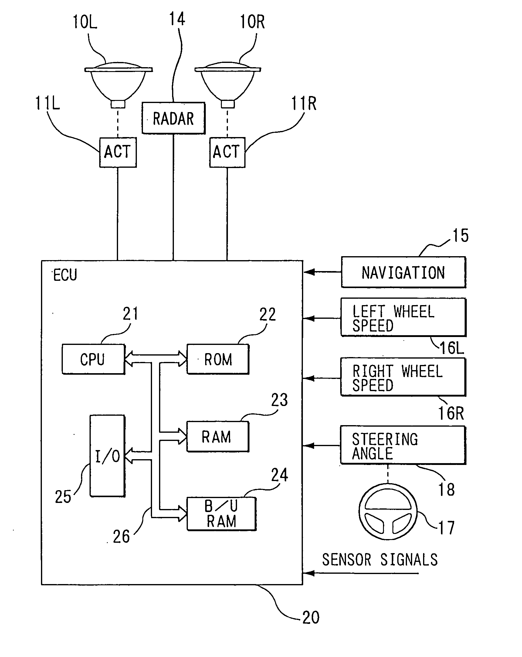
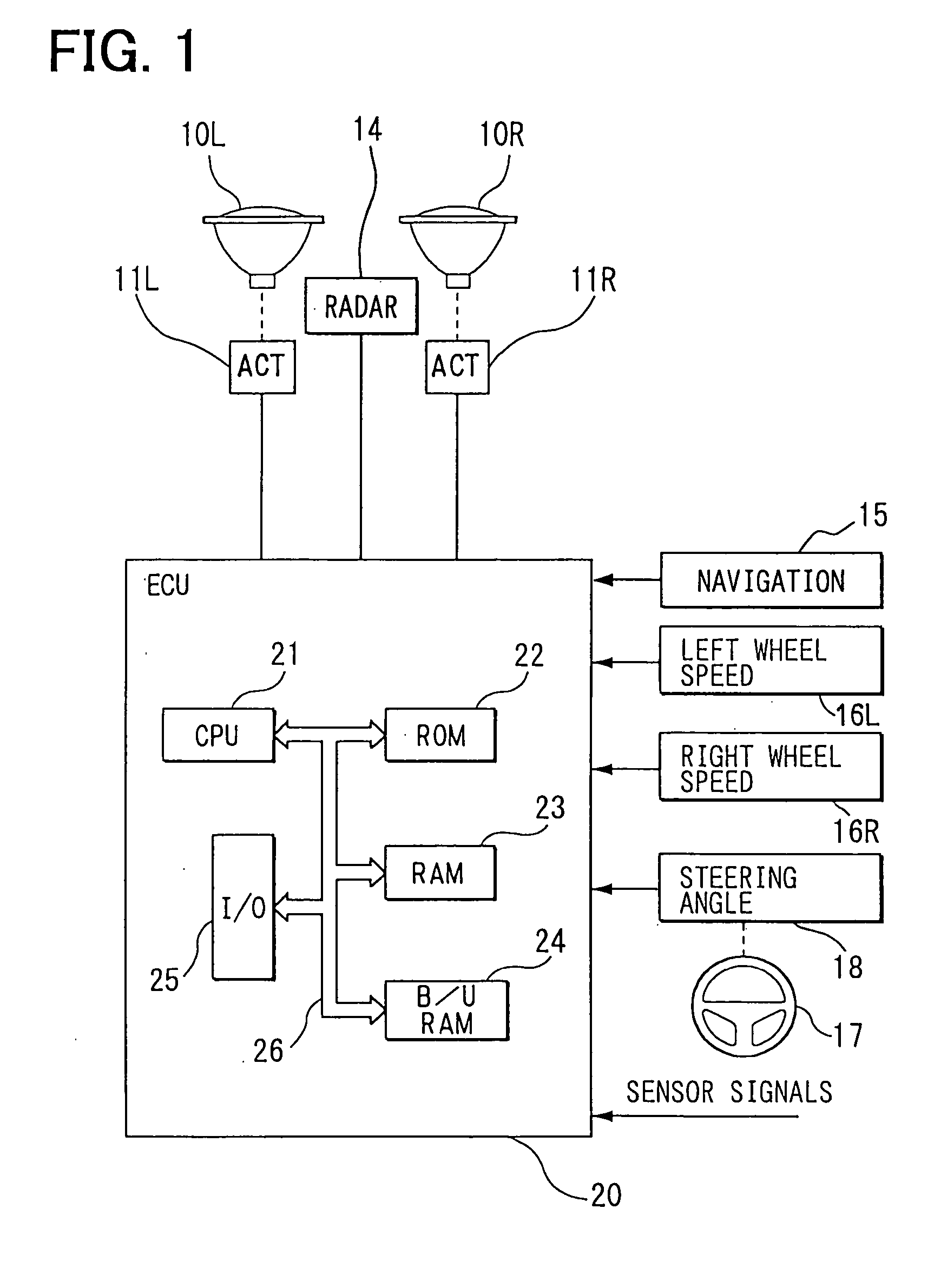
[0029] In the first embodiment, as shown in FIG. 1, left and right headlights 10L, 10R are provided on a front side of a vehicle. Actuators 11L, 11R for adjusting an optical axis direction are connected to the left and right headlights 10L, 10R respectively. An electric control unit (ECU) 20 is provided for controlling the optical axis direction of the vehicle headlight. It includes a well-known central processing unit (CPU) 21, a read only memory (ROM) 22, a random access memory (RAM) 23, a backup RAM 24, an input / output circuit 25 and a bus line 26 which connects the above devices. The CPU 21 performs various operations and processing. The ROM 22 stores a control program, a control characteristic of the optical axis direction of the left and right headlights 10L, 10R and the like. The RAM 23 stores various data.

[0030] Output signals from a well-known navigation system 15, a left wheel speed sensor 16L for detecting a left wheel speed, a right wheel speed s...

second embodiment

[0040] (Second Embodiment)

[0041] In the second embodiment, an automatic optical axis direction adjusting device for a vehicle headlight is constructed similarly to the first embodiment. However, a well-known laser radar 14 is additionally provided as shown in FIG. 1 in order to measure a distance between a vehicle and a preceding vehicle. The laser radar 14 is disposed, for example, in a front bumper. An output signal from the laser radar 14 is also inputted to the ECU 20.

[0042] A swivel control process in FIG. 4 is repeated every predetermined control time. At step S204, a distance D between the vehicle and a preceding vehicle is read from the laser radar 14. At step S205, the information for VICS in the forward road information DNAVI from the navigation system 15 is read. The forward road information DNAVI includes geographical map information, a vehicle position, landmarks and the like in addition to the information for VICS.

[0043] At step S206, a threshold distance Dth between t...

third embodiment

[0050] (Third Embodiment)

[0051] An automatic optical axis direction adjusting device for a vehicle headlight according to the third embodiment is a modification of that of the second embodiment.

[0052] Similarly to the first and the second embodiment, a swivel control process in FIG. 6 is repeated every predetermined control time. At step S305, it is decided whether a number LM of landmarks in a predetermined area from the vehicle position is more than a predetermined number LMth. The vehicle position and the number LM can be obtained based on the forward road information DNAVI read at step S104. When it is decided that the number LM is more than the number LMth at step S305, it is decided that the vehicle runs in a city area. In this case, a control characteristic is switched to stop an adjustment of the optical axis direction. That is, at step S306, the swivel control angle SWC is set to 0. Thereafter, the swivel control process proceeds to step S307.

[0053] At step S307, the optica...


PUM


Abstract

In an automatic optical axis direction adjusting device for a vehicle headlight, a control characteristic is switched according to a road condition, a designation by a user or the like. Therefore, the optical axis direction of the vehicle headlight can be adjusted to suit a vehicle driving condition, a driver's preference or the like without causing a driver to feel uncomfortableness. Furthermore, the adjustment of the optical axis direction can be stopped or restricted according to the switched control characteristic. Therefore, unnecessary operation of a driving system such as an actuator can be avoided to increase durability.

Description

[0001] This application is based on Japanese Patent Applications No. 2003-116056 filed on Apr. 21, 2003 and No. 2004-38166 filed on Feb. 16, 2004, the disclosures of which are incorporated herein by reference.[0002] 1. Field of the Invention[0003] The present invention relates to an automatic optical axis direction adjusting device for a vehicle headlight, which automatically controls the optical axis direction or a lighting range of the vehicle headlight according to a steering angle of a steering wheel.[0004] 2. Description of Related Art[0005] An automatic optical axis direction adjusting device for a vehicle headlight is disclosed, for example, in JP-A-H3-14742, JP-A-S64-74133, JP-A-H8-301005, JP-A-H11-235949 and JP-A-2002-234381.[0006] In JP-A-H3-14742, a lighting angle of a headlight is set suitably based on a control characteristic according to a steering wheel position.[0007] In JP-A-S64-74133, a change of a lighting direction of a headlight which is operated together with a...

Claims


Application Information

Patent Timeline
IPC IPC(8): B60Q1/12
CPCB60Q1/12B60Q2300/112B60Q2300/122B60Q2300/21B60Q2300/322B60Q2300/332B60Q2300/333B60Q2300/41
Inventor MIZUNO, RYUISHIGURO, KOJIKAIBA, KAZUHIKO
Owner DENSO CORP
Why Eureka
Try Eureka