Eureka AIR delivers breakthrough ideas for toughest innovation challenges, trusted by R&D personnel around the world.

Cleaning unit, slit coating apparatus having the same and method of coating substrate

Active Publication Date: 2004-10-28
SAMSUNG DISPLAY CO LTD
View PDF7 Cites 28 Cited by
  • Summary
  • Abstract
  • Description
  • Claims
  • Application Information

AI Technical Summary

Benefits of technology

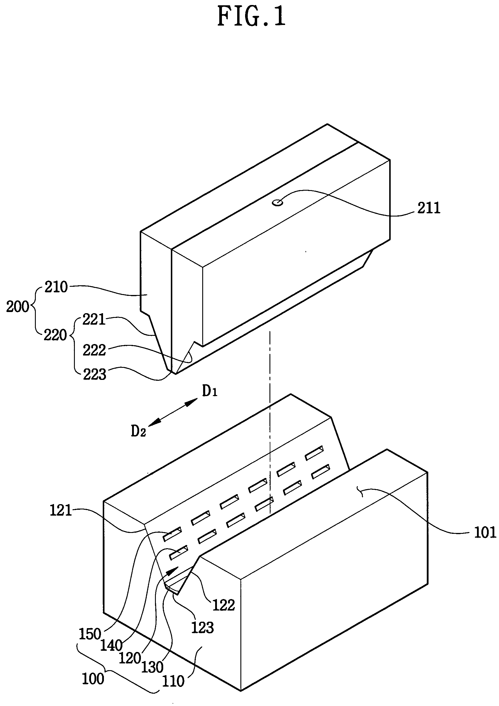
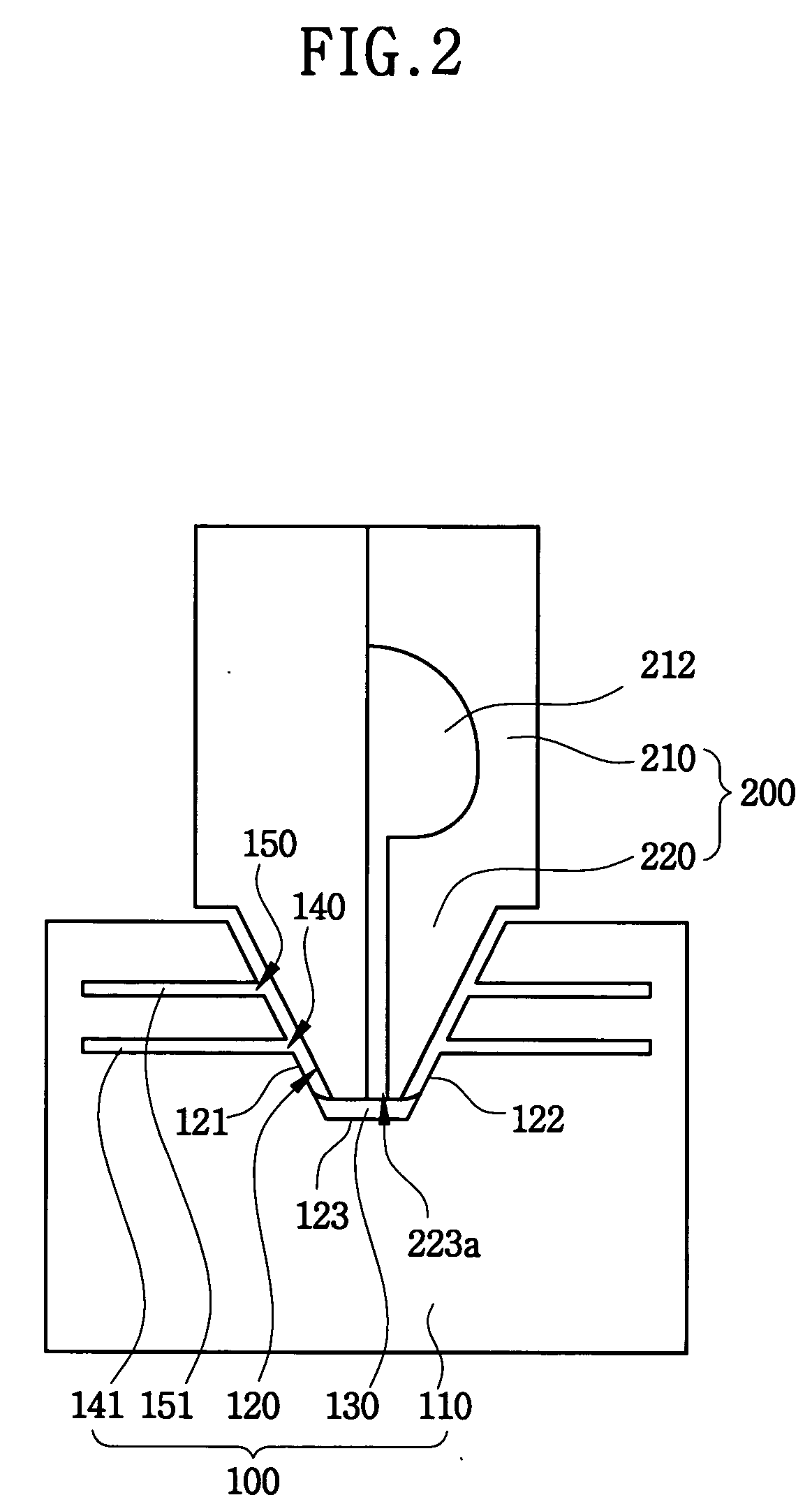
[0014] According to the cleaning unit of this invention, the cleaning unit for cleaning a slit coater for coating materials on a substrate includes a body and a cleaning member. The body includes an upper face. The upper face subsides to form a receiving recession for receiving a slit nozzle of the slit coater. The receiving recession includes a sidewall and a bottom face. The sidewall includes a first injection hole. A cleaning material is sprayed via the injection hole. The cleaning member eliminates dregs of the material attached on the slit nozzle of the slit coater. The cleaning member is attached on the bottom face of the receiving recession.
[0015] According to the slit coating apparatus of the present invention, the slit coating apparatus includes a supporting member, a slit coater and a cleaning unit. The supporting member supports a substrate. The slit coater coats the substrate with predetermined material. The slit coater includes a slit nozzle having a slit for discharging the material. The cleaning unit cleans the slit coater. The cleaning unit includes a body and a cleaning member. The body includes an upper face. The upper face subsides to form a receiving recession for receiving a slit nozzle of the slit coater. The receiving recession includes a sidewall and a bottom face. The sidewall includes a first injection hole. A cleaning material is sprayed via the injection hole. The cleaning member eliminates dregs of the material attached on the slit nozzle of the slit coater. The cleaning member is attached on the bottom face of the receiving recession.
[0017] According to the cleaning unit, the slit coating apparatus having the cleaning unit, and the method of coating a substrate of the present invention, the slit coater is cleaned before or after the slit coater forms the photosensitive layer on the substrate with the photosensitive material. The cleaning unit includes the first injection hole through which the cleaning material is sprayed, and the cleaning member for rubbing the substrate so as to eliminate the dregs.
[0018] Therefore, the slit nozzle is effectively cleared, so that the substrate is uniformly coated with the photosensitive layer, and the photosensitive layer is not scratched.

Problems solved by technology

When the photosensitive material is not coated uniformly, deterioration occurs in next processes.
However, the spin coating method is not preferable in order that the substrate of a liquid crystal display panel is coated with the photosensitive material, because the substrate of the liquid crystal display device is heavy and large.
When the substrate of the liquid crystal display device is heavy and large, rotating the substrate is hard, and the substrate is damaged (or broken) easily.
However, when the slit coater repeats coating operation, dregs are attached on the slit nozzle of the spin coater, so that a uniformity of a photosensitive layer formed on the substrate is deteriorated.
As a result, a display quality of the liquid crystal display device is deteriorated.

Method used


Image

  • Cleaning unit, slit coating apparatus having the same and method of coating substrate
  • Cleaning unit, slit coating apparatus having the same and method of coating substrate
  • Cleaning unit, slit coating apparatus having the same and method of coating substrate

Examples


second embodiment

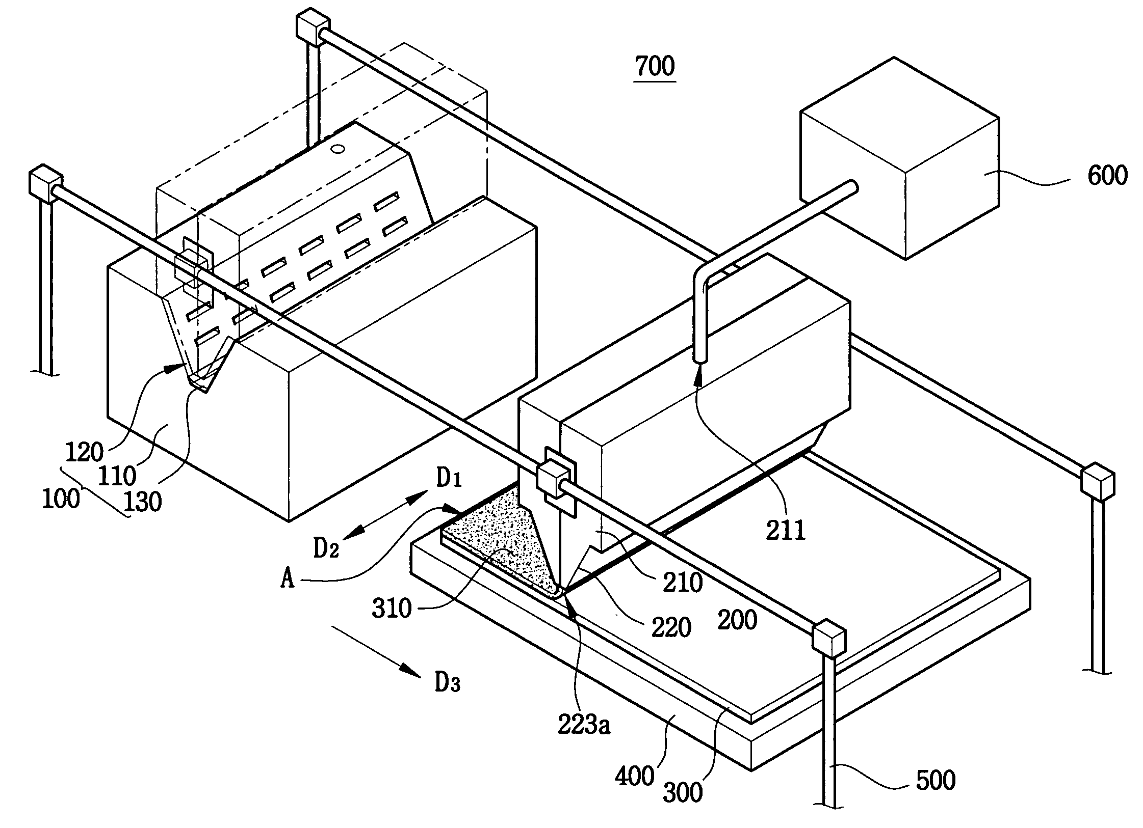
[0049] FIG. 3 is a perspective view showing a slit coating apparatus according to the present invention. In FIG. 3, the same reference numbers will be used to refer to the same or like parts as those shown in FIG. 1.

[0050] Referring to FIGS. 1, 2 and 3, a slit coating apparatus 700 according to a second embodiment of the present invention includes a supporting member 400. The supporting member 400 supports a substrate 300 so as to coat the substrate 300 with a photosensitive layer 310. The supporting member 300 makes contact with a second face of the substrate 300. The second face of the substrate 300 faces a first face of the substrate 300. The first face of the substrate 300 is coated with the photosensitive layer 310.

[0051] The slit coating apparatus 700 also includes a slit coater 200 for coating the photosensitive layer 310 on the first face of the substrate 300. The silt coater 200 includes a coater body 210 and a slit nozzle 220.

[0052] A photosensitive material supplying unit...

third embodiment

[0058] FIG. 4 is a flow chart showing a method of coating according to the present invention.

[0059] Referring to FIGS. 3 and 4, the receiving recession 120 of the cleaning unit 100 receives the slit nozzle 220. The cleaning material is sprayed via the first injection hole 140 of the receiving recession 120 toward the slit nozzle 220, while the cleaning unit 100 moves in the first direction D.sub.1. Then the dregs of the photosensitive material are saturated with the cleaning material (step S10).

[0060] The connection face 223 of the slit nozzle 220 makes contact with the cleaning member 130. Therefore, when the cleaning unit 100 moves in the first direction D1, the cleaning member 130 scrubs the connection face 223 to eliminate the dregs (step S20).

[0061] The gas is sprayed via the second injection hole 150 toward the slit nozzle 220, while the cleaning unit 100 moves in the second direction D.sub.2 so as to dry the slit nozzle 220 (step S30). When the slit nozzle 220 is dried, the p...


PUM


Abstract

A cleaning unit of this invention includes a body and a cleaning member. The body includes an upper face. The upper face subsides to form a receiving recession for receiving a slit nozzle of the slit coater. The receiving recession includes a sidewall and a bottom face. The sidewall includes a first injection hole. A cleaning material is sprayed via the injection hole. The cleaning member eliminates dregs of the material attached on the slit nozzle of the slit coater. The cleaning member is attached on the bottom face of the receiving recession. According to the present invention, the slit nozzle is effectively cleared, so that the substrate is uniformly coated with the photosensitive layer, and the photosensitive layer is not scratched.

Description

[0001] This application relies for priority upon Korean Patent Application No. 2003-25695 filed on Apr. 23, 2003, the contents of which are herein incorporated by reference in its entirety.[0002] 1. Field of the Invention[0003] The present invention relates to a cleaning unit, a slit coating apparatus having the cleaning unit, and a method of coating a substrate, more particularly to a cleaning unit enhancing efficiency of coating process, a slit coating apparatus having the cleaning unit, and a method of coating a substrate.[0004] 2. Description of the Related Art[0005] In general, a photosensitive material is used for patterning a thin film that performs a special function. The photosensitive material chemically reacts on light. When the photosensitive material is not coated uniformly, deterioration occurs in next processes.[0006] When the photosensitive material is coated thicker than a predetermined thickness on a thin film, the thin film is under-etched. When the photosensitive...

Claims


Application Information

Patent Timeline
IPC IPC(8): B05B15/02B05C5/02G02F1/13B05C11/10B05D3/00B08B3/02
CPCB05B15/025B05C5/0254B05B15/555G02F1/13
Inventor JUNG, SUNG-KIKANG, HO-MIN
Owner SAMSUNG DISPLAY CO LTD
Why Eureka
Eureka Blog
Learn More