
Integrated purge store mechanism to flush L2/L3 cache structure for improved reliabity and serviceability

a cache structure and purge store technology, applied in the field of computer systems, can solve the problems of inability to determine what the proper data stream should actually be, inability to detect soft errors, and inability to clean cache structures,

Active Publication Date: 2004-10-28
TWITTER INC
View PDF3 Cites 22 Cited by
  • Summary
  • Abstract
  • Description
  • Claims
  • Application Information

AI Technical Summary

Problems solved by technology

However, if the data in the chosen block is not modified, the block is simply abandoned and not written to the next lowest level in the hierarchy.
These commands often result when a device issues a read-with-intent-to-modify (RWITM) instruction.
Flush instructions can be used to walk through the entire cache memory as part of a shut-down, but this procedure can sometimes take an inordinate amount of time.
One problem with these cache constructions relates to so-called "soft" errors that might arise from, e.g., stray radiation or electrostatic discharge.
Most ECCs in use correct only single-bit errors, i.e., if two or more bits in a particular block are invalid, then the ECC might not be able to determine what the proper data stream should actually be, but at least the failure can be detected.
In particular, problems with soft errors in large caches can lead to uncorrectable errors when a second soft error arises in the same block as a preexisting soft error.
With the eviction mechanism of the cache placed in a direct-mapped mode, the address misses will result in eviction of the cache lines.

Method used


Image

  • Integrated purge store mechanism to flush L2/L3 cache structure for improved reliabity and serviceability
  • Integrated purge store mechanism to flush L2/L3 cache structure for improved reliabity and serviceability
  • Integrated purge store mechanism to flush L2/L3 cache structure for improved reliabity and serviceability

Examples


Embodiment Construction

)

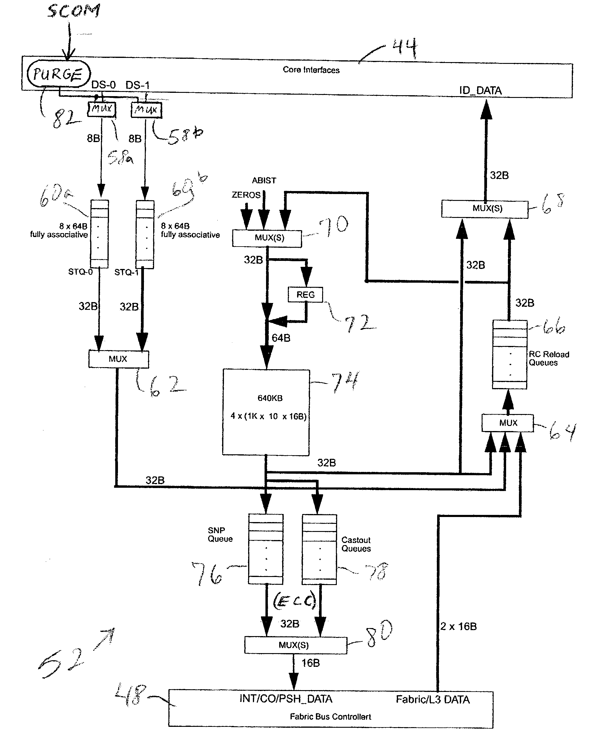
[0027] The present invention is directed to an improved cache construction which is able to "scrub" the values stored in the cache memory, to purge any correctable errors in those stored values so as to reduce the likelihood of an uncorrectable error arising. For caches which utilize error correction code (ECC) having single-bit correct / double-bit detect capability (SBC / DBD), an uncorrectable error might arise if a first soft error is already present but uncorrected in a particular cache line, and then a second soft error is introduced to the same line. If a double-bit error in the line is detected, the machine must be brought to a halt. The present invention accordingly decreases the likelihood of any such system down time.

[0028] While the invention is generally applicable to any type of memory hierarchy having one or more caches, including non-uniform memory access (NUMA) structures, it is particularly useful for larger caches which require improved reliability. In the illustrati...


PUM


Abstract

A method of reducing errors in a cache memory of a computer system (e.g., an L2 cache) by periodically issuing a series of purge commands to the L2 cache, sequentially flushing cache lines from the L2 cache to an L3 cache in response to the purge commands, and correcting errors (single-bit) in the cache lines as they are flushed to the L3 cache. Purge commands are issued only when the processor cores associated with the L2 cache have an idle cycle available in a store pipe to the cache. The flush rate of the purge commands can be programmably set, and the purge mechanism can be implemented either in software running on the computer system, or in hardware integrated with the L2 cache. In the case of the software, the purge mechanism can be incorporated into the operating system. In the case of hardware, a purge engine can be provided which advantageously utilizes the store pipe that is provided between the L1 and L2 caches. The L2 cache can be forced to victimize cache lines, by setting tag bits for the cache lines to a value that misses in the L2 cache (e.g., cache-inhibited space). With the eviction mechanism of the cache placed in a direct-mapped mode, the address misses will result in eviction of the cache lines, thereby flushing them to the L3 cache.

Description

[0001] The present application is related to copending U.S. Patent Application No. 10 / ______ entitled "DATA CACHE SCRUB MECHANISM FOR LARGE L2 / L3 DATA CACHE STRUCTURES" filed contemporaneously herewith on or about Apr. 24, 2003, attorney docket number AUS920030128US1.[0002] 1. Field of the Invention[0003] The present invention generally relates to computer systems, and more particularly to a method of scrubbing or purging a memory system such as a cache memory, to facilitate serviceability and decrease the likelihood of multiple uncorrectable errors which would otherwise cause a system halt.[0004] 2. Description of the Related Art[0005] The basic structure of a conventional computer system 10 is shown in FIG. 1. Computer system 10 may have one or more processing units, two of which 12a and 12b are depicted, which are connected to various peripheral devices, including input / output (I / O) devices 14 (such as a display monitor, keyboard, and permanent storage device), memory device 16 (...

Claims


Application Information

Patent Timeline
Patent Type & Authority Applications(United States)
IPC IPC(8): G06F12/08
CPCG06F12/0804G06F12/0897
Inventor CARGNONI, ROBERT ALANGUTHRIE, GUY LYNNREICK, KEVIN FRANKLINWILLIAMS, DEREK EDWARD
Owner TWITTER INC
Features
  • Generate Ideas
  • Intellectual Property
  • Life Sciences
  • Materials
  • Tech Scout
  • Unparalleled Data Quality
  • Higher Quality Content
  • 60% Fewer Hallucinations
Learn More