Microprocessor comprising operating modes with low current consumption

a microprocessor and operating mode technology, applied in the field of microprocessors, can solve the problems of unjustified excess consumption, high current consumption, and considerable electric power consumption of mode run

Active Publication Date: 2004-11-04
STMICROELECTRONICS SRL
View PDF1 Cites 40 Cited by
  • Summary
  • Abstract
  • Description
  • Claims
  • Application Information

AI Technical Summary

Problems solved by technology

The mode RUN has the disadvantage of requiring considerable electric power since all the circuits of the microprocessor are awakened at their nominal frequency, very high (the consumption of an integrated circuit varies essentially according to the switch rate of the transistors).
However, the current consumption remains high since the central processing unit and all the peripheral circuits are active, particularly the quartz oscillator circuit OSC, that is a high consuming item.
Therefore, in microprocessors of known type, during the operation in the halt mode HALT, upon each periodical wake-up, the CPU, the clock circuits and all the peripheral circuits must wake themselves up in the execution mode RUN for a certain number of clock cycles, even if it transpires that there are no operations to be performed, which represents an unjustified excess consumption.
The defect of the microprocessors described above is that they require a high number of stabilization cycles upon the wake-up of the main clock circuit and of the CPU.
The disadvantage of this state of the art is that the circuits of the oscillator and of the central processing unit consume considerable electric power during this stabilization time, unnecessarily, without performing any operation.
Therefore, absurdly, the CPU wakes itself up and consumes electric power, in an unjustified manner, during the stabilization cycles, while it transpires that there are no operations to be performed.

Method used


Image

  • Microprocessor comprising operating modes with low current consumption
  • Microprocessor comprising operating modes with low current consumption
  • Microprocessor comprising operating modes with low current consumption

Examples


Embodiment Construction

EN1 EN2 SELCK CK X X X 0 (RESET) MD0 (HALT) 0 0 X 0 1 0 0 (inhibited) 0 (RESET) Md1 (RUN) 1 0 0 CK1 1 0 1 0 0 (RESET) MD2 (LOW 0 1 1 CK2 1 (inhibited) PWR) 1 1 0 0 (CNT) MD3 1 1 1 CK2 (SWITCH) 0 1 Change from 1 1 1 CK2 1 1 MD3 to MD1 1 1 0 CK1 (RUN

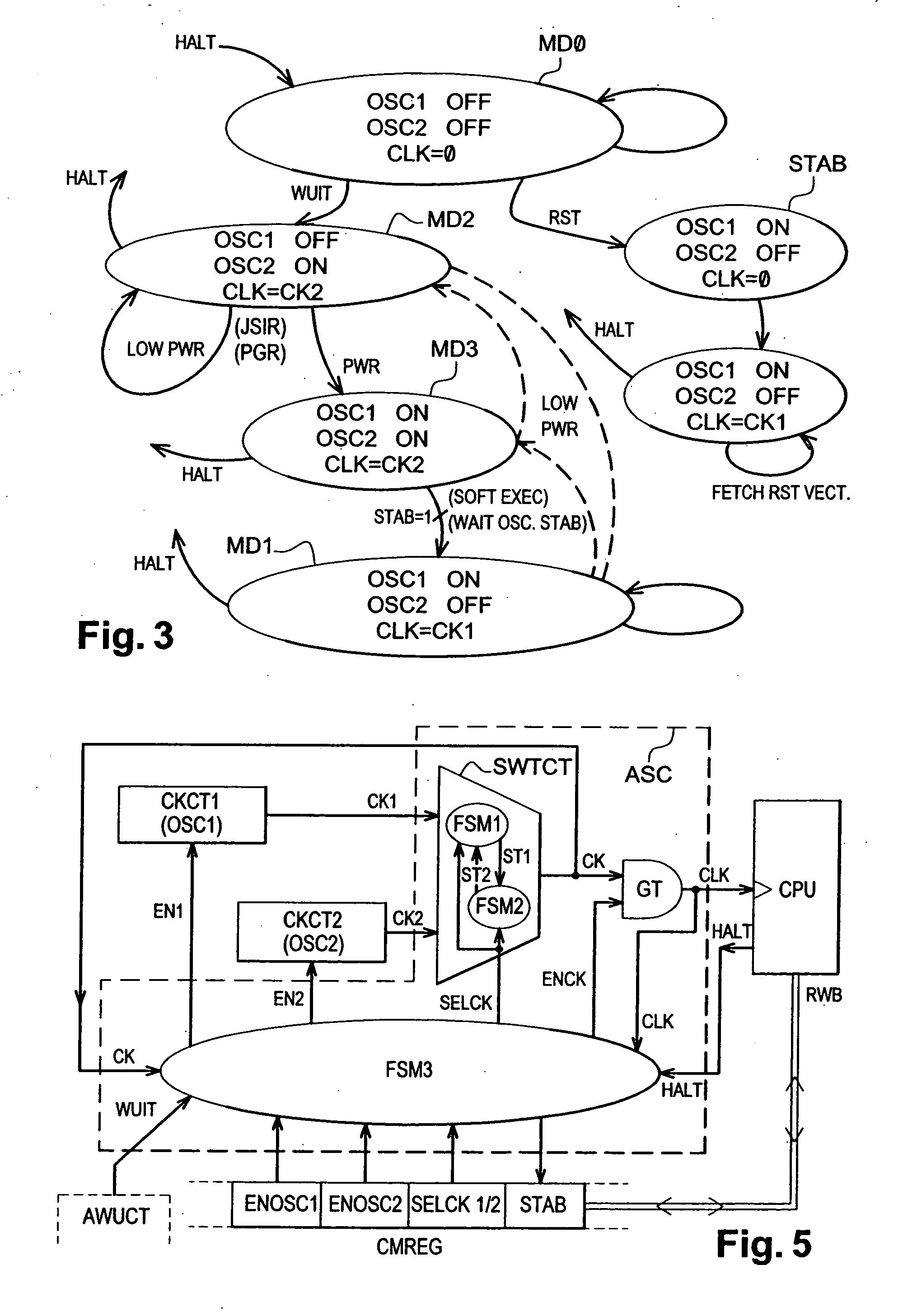
[0148] Provision is made so that the circuit of the register CMREG does not authorize the CPU to simultaneously set the flags ENOSC1 and ENOSC2 to the level 0. As appropriate, the register CMREG keeps the former values X of the flags ENOSC1 and ENOSC2, such that at least one of the flags ENOSC1 and / or ENOSC2 is on the level 1. This set point allows one of the two oscillators OSC1 or OSC2 to be awakened automatically when the CPU wakes up at the end of mode HALT.

[0149] On the other hand, in the mode HALT precisely, as explained above with regard to the step 33 in FIG. 8, the control circuit FSM3 sets the two signals EN1 and EN2 to the level 0, which effectively deactivates the two oscillators OSC1 and OSC2 simultaneously, even if at least o...


PUM


Abstract

The present invention relates to an integrated circuit comprising a central processing unit clocked by a clock signal, a main oscillator circuit supplying a first clock signal and a peripheral circuit supplying a periodic wake up signal, the central processing unit comprising a first operating mode at full power, in which the first clock signal is applied to the central processing unit, and an active halt mode in which the main oscillator circuit and the central processing unit are deactivated, the central processing unit being awakened by the periodic wake-up signal. According to the present invention, the integrated circuit comprises a secondary oscillator circuit for supplying a second clock signal of lower frequency than the first clock signal and a circuit for managing clock signals arranged for, upon the wake-up of the central processing unit at the end of the active halt mode, waking up the secondary oscillator circuit and applying the second clock signal to the central processing unit so as to clock the central processing unit to the lower frequency of the second clock signal and thus obtain a second operating mode with reduced current consumption relative to the first operating mode.

Description

[0001] 1. Field of the Invention[0002] The present invention relates to microprocessors and more particularly the generation of clock signals in the microprocessors and the operating modes of the microprocessors.[0003] 2. Description of the Related Art[0004] FIG. 1 represents the structure of a classical microprocessor. The microprocessor comprises a central processing unit CPU for performing the program operations in connection with a memory MEM allowing the data and the program instructions to be stored. The operation of the CPU is clocked by a main clock signal CLK coming from a clock generation circuit comprising a quartz X oscillator circuit OSC. A frequency divider circuit PSC (prescaler) lowers the frequency of the signal CKO coming from the oscillator OSC and delivers the main clock signal CK1 that determines the nominal working frequency of the CPU. Another frequency divider circuit DCT is bypass positioned on the line of the main clock signal CK1 to supply another clock si...

Claims


Application Information

Patent Timeline
Patent Type & Authority Applications(United States)
IPC IPC(8): G06F1/32
CPCG06F1/3203Y02B60/1217Y02D10/00
Inventor DURAND, BENOITLACAN, JEROME
Owner STMICROELECTRONICS SRL
Why Eureka
Try Eureka