Gear, and method and apparatus for manufacturing the same

a technology for making gear and gear parts, applied in the field of gear, can solve the problems of affecting the quality of gear parts, and difficulty in forming optional forms,

Active Publication Date: 2004-11-25
O OKA CORP
View PDF8 Cites 15 Cited by
  • Summary
  • Abstract
  • Description
  • Claims
  • Application Information

AI Technical Summary

Problems solved by technology

Cutting process has problems such as attrition of tools, occurrence of chips, difficulty of forming optional form and requiring long machining time.
Therefore, chamfering is inefficient and needs amount of time.

Method used


Image

  • Gear, and method and apparatus for manufacturing the same
  • Gear, and method and apparatus for manufacturing the same
  • Gear, and method and apparatus for manufacturing the same

Examples


embodiment

[0040] (Embodiment)

[0041] A gear of the present embodiment having a part worked by cutting and the other process as shown in FIGS. 1-3 wherein a chamfer part is formed at least in a portion between a tooth part formed on an outer peripheral surface and an end part thereof in an axial direction by a forging process.

[0042] A gear of the present embodiment, by way of example, is an idler gear used for automobile transmission according to the techniques of the present invention.

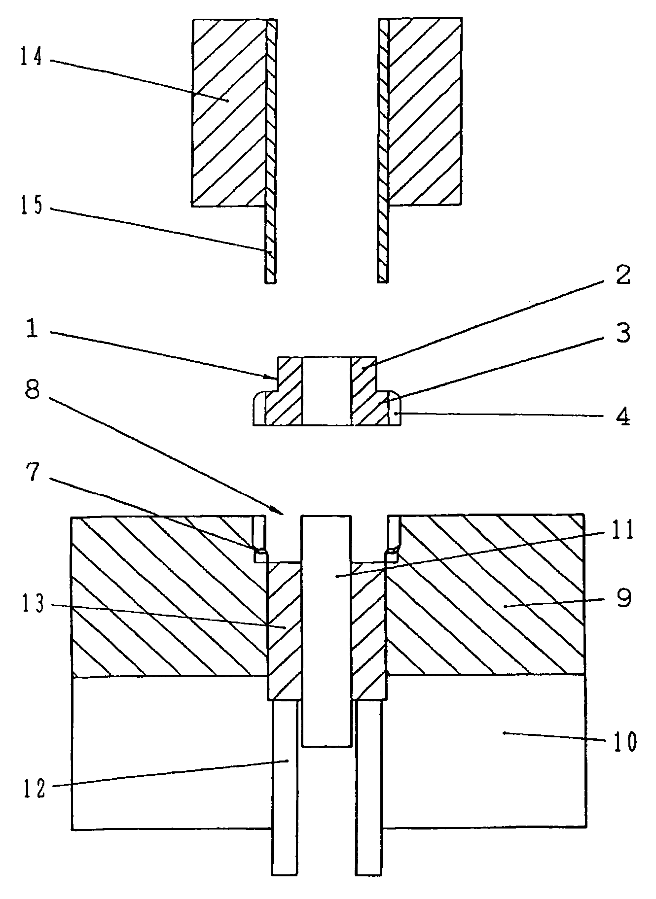
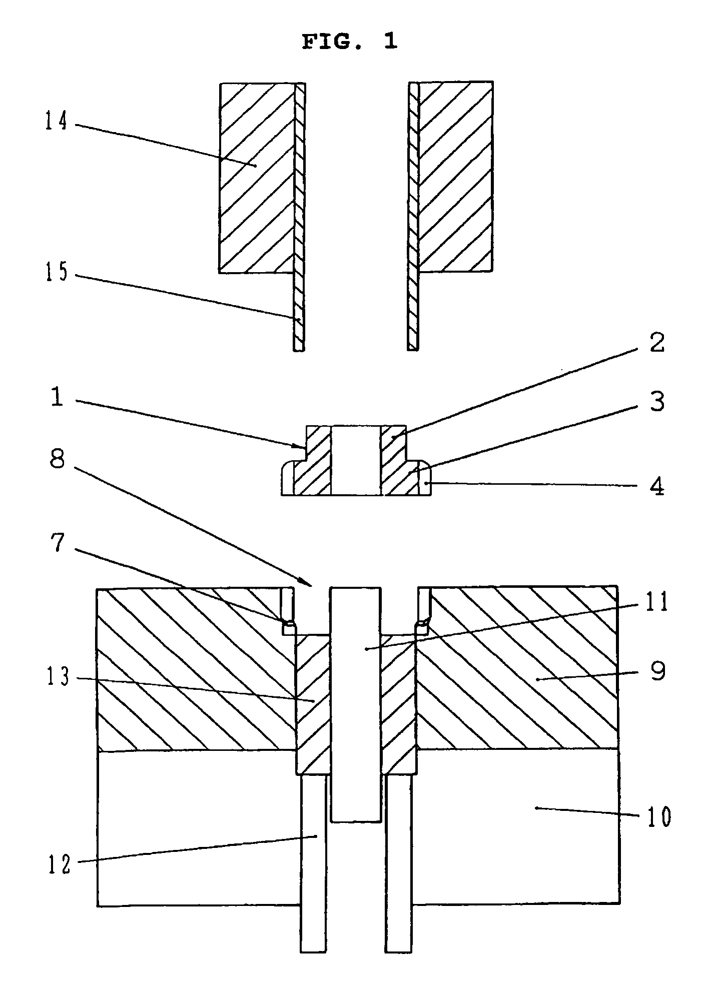
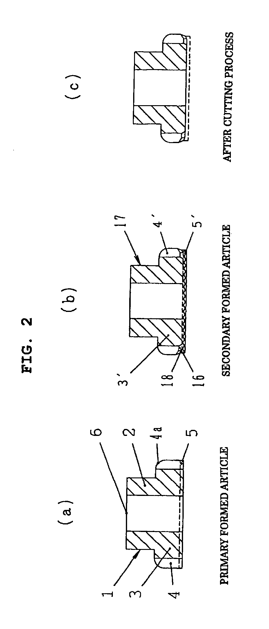
[0043] FIG. 1 shows a forging device for forming a chamfer part at an end part of tooth form of primary formed article. As shown in FIG. 2(a) a primary formed article 1 comprises tooth form 4 with a chamfer 4a around a gear part 3 formed at an end part of hub part 2, and the chamfer 4a is formed on the side of hub part 2 of tooth part 4. Pads 5 project to the other side. Axial hole 6 is formed at the center.

[0044] The inner circumferential surface of the forging device is formed as a tooth-shaped form correspondi...

example

[0051] In the Examples of the present invention, the end of the chamfer part formed connected to the whole outer peripheral surface of said tooth part corresponds to the cut surface. By forging technique, whatever form of the chamfer part can be formed in response to a final form easily. Therefore, according to the present examples the chamfer part can remain 100% on the products worked by cutting, weld flash scarcely occur and an effect of forging process function effectively and rationalistically.

[0052] Although, in the present invention, the chamfer part formed by forging process remains 100% in order to avoid the occurrence of weld flash. Therefore, it is enough to obtain the same effect that tooth part and the cut part are at different position each other, the tooth part and the cut part keep a distance each other and the small chamfer part remains.

[0053] In the example the secondary formed article is an article formed the chamfer part at the end corner part on the opposite sid...


PUM

PropertyMeasurementUnit
elongationaaaaaaaaaa
timeaaaaaaaaaa
degree of freedomaaaaaaaaaa

Abstract

Idler gear as an example of gears having a part worked by cutting, and method and apparatus for manufacturing the same in which the chamfer part is formed at least in a portion between a tooth form with chamfers formed by forging process on an outer peripheral surface and the end part thereof in the axial direction by cutting.

Description

[0001] This invention relates to a gear having side faces worked by cutting and a method and apparatus for manufacturing the same.TECHNICAL BACKGROUND[0002] A gear formed by forging process has pads projecting at least to a pressurized side surface. Cutting process is applied to the side surface in order to cut off the projecting part of the pads.[0003] A weld flash occurs on an elongation of cut surface of tooth surface on the gear owing to the cutting process. Generally chamfering is carried out to a corner part in order to finish the corner part having the weld flash and this chamfering has been carried out by cutting.[0004] Cutting process has problems such as attrition of tools, occurrence of chips, difficulty of forming optional form and requiring long machining time. Particularly, chamfering must be carried out one tooth at a time by turns. Therefore, chamfering is inefficient and needs amount of time.[0005] Furthermore, when chamfering is carried out by cutting process in or...

Claims


Application Information

Patent Timeline
Patent Type & Authority Applications(United States)
IPC IPC(8): B21K1/30B23P15/14
CPCB21K1/30B23P15/14Y10T74/19958Y10T29/49476Y10T74/19851Y10T74/19972Y10T29/49474Y10T74/19949
Inventor KIMURA, MAKOTO
Owner O OKA CORP
Why Eureka
Try Eureka