
Apparatus for monitoring a smoke detector

a smoke detector and apparatus technology, applied in the direction of fire alarms, smoke/gas actuation, fire alarms, etc., can solve the problems of affecting the proper function preventing the proper functioning of the smoke detector, and unable to work with the smoke detector, so as to prevent the erroneous reaction and prevent the wrong measurement of the pressure differential in the air flow passage

Active Publication Date: 2004-12-09
AIRBUS OPERATIONS GMBH
View PDF4 Cites 11 Cited by
  • Summary
  • Abstract
  • Description
  • Claims
  • Application Information

AI Technical Summary

Benefits of technology

[0007] to facilitate a continuous monitoring of the smoke detectors in an aircraft;
[0011] According to the invention it is an advantage that the smoke detector or detectors in an aircraft are monitored on a continuous or permanent basis by making sure that any smoke that is generated can freely pass to the respective smoke detector inlet without any flow reduction and without any flow prevention. Another important advantage of the invention is seen in that a wrong measurement of a pressure differential in the air flow passage can be prevented by timing the operation of the air pressure sensors, thereby preventing an erroneous reaction in case of pressure fluctuation of very short durations, for example when a vacuum toilet is activated. Furthermore, it is advantageous that a blockage or partial clogging of the air flow passage can be automatically reported to a location outside the enclosure in which the smoke detector is installed. Thus, the display or indication of the signal that signifies such a blockage or clogging may be made visible or audible anywhere within the aircraft, particularly outside the space in which the smoke detector is installed, such as a toilet or freight space. The respective signals may be transmitted to a monitor of a central maintenance system, whereby the monitor may be located, for example, in the cockpit of the aircraft.

Problems solved by technology

The smoke detector cannot work if the smoke cannot get to the smoke detector.
In areas in which unfiltered air is circulating such as in a freight space, the air flow passage leading to a smoke detector may be obstructed or even completely blocked quite quickly, which leads to impairing or even preventing the proper function of the smoke detector.

Method used


Image

  • Apparatus for monitoring a smoke detector
  • Apparatus for monitoring a smoke detector

Examples


Embodiment Construction

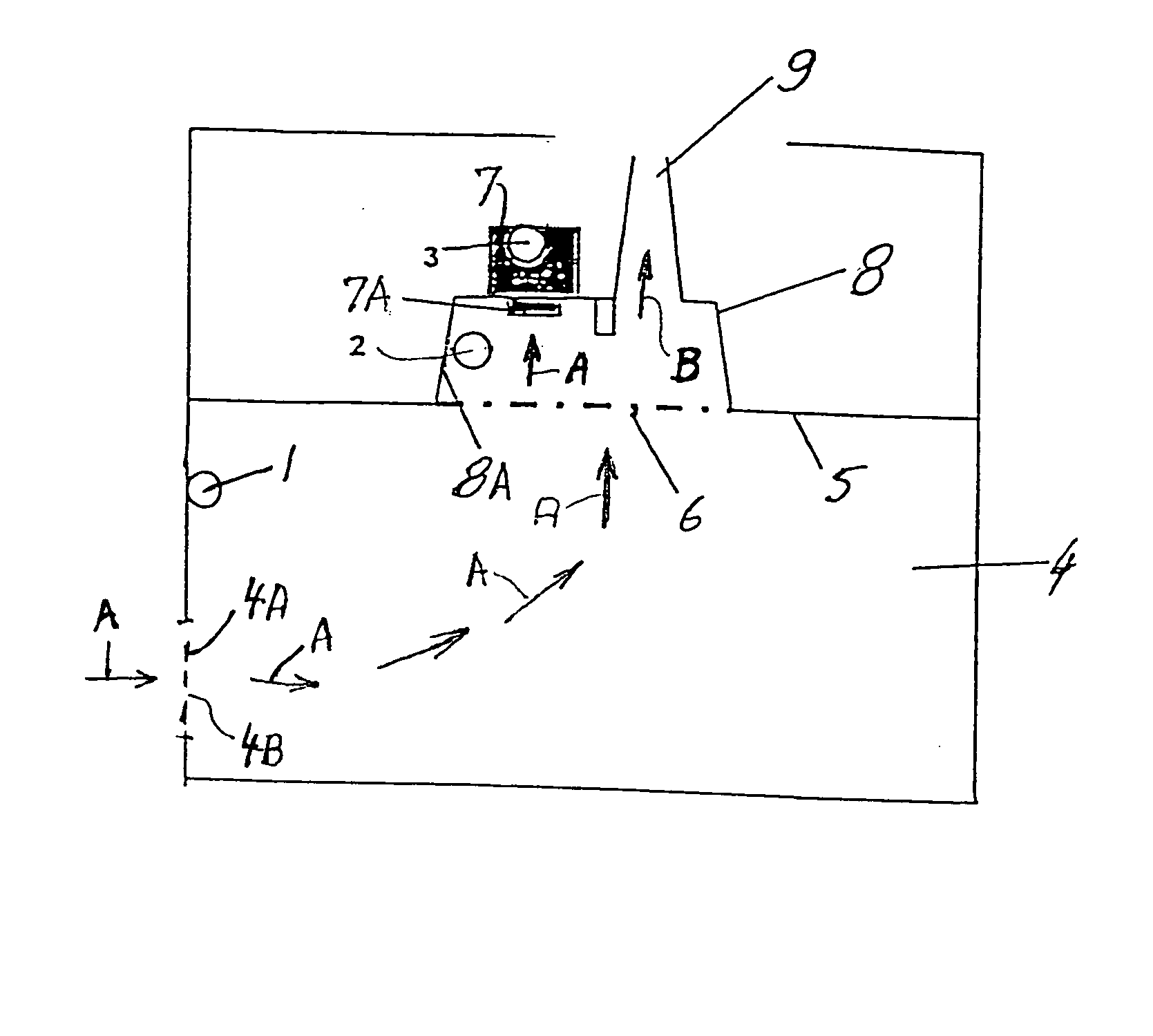
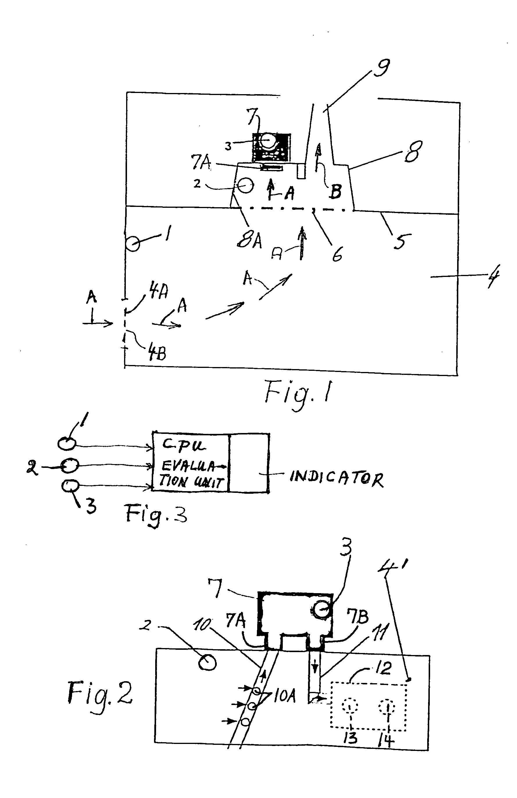
[0016] FIG. 1 shows schematically an aircraft toilet 4 having a door 4A in which an air inlet 4B is installed. Arrows A indicate an air flow passage which is also a smoke flow passage since the air flow transports any smoke generated in the toilet or within a smoke detector housing 8 to the smoke detector 7 installed above a toilet ceiling 5. A protective grid or screen structure 6 separates the smoke detector housing 8 from the toilet space below the ceiling 5. The smoke detector housing 8 forms a hood in which normally a fan is installed for generating the air flow A and an exhaust air flow B through a used air discharge channel 9 leading out of the smoke detector housing or hood 8.

[0017] In the example embodiment of FIG. 1, three air pressure sensors 1, 2 and 3 are installed in the vicinity of the smoke detector 7 whose air inlet 7A faces into the smoke detector housing 8. One air pressure sensor 1 is installed inside the toilet 4. Another air pressure sensor 2 is secured to the ...


PUM


Abstract

The proper function of a smoke detector of an enclosed space, such as a toilet or freight space or crew quarters in an aircraft, is monitored by at least two air pressure sensors which are so positioned that these air pressure sensors can measure an air pressure differential in the air flow into the smoke detector. If a pressure differential is detected the differential is evaluated in a central processing unit which produces a respective signal that indicates that the air flow and thus the smoke flow into the smoke detector is obstructed, whereby the smoke detector cannot function properly. This signal is visibly or audibly indicated.

Description

PRIORITY CLAIM[0001] This application is based on and claims the priority under 35 U.S.C. .sctn.119 of German Patent Application 103 19 688.9, filed on May 2, 2003, the entire disclosure of which is incorporated herein by reference.[0002] The invention relates to an apparatus for monitoring a smoke detector and visually displaying and / or audibly announcing detected information in an aircraft.BACKGROUND INFORMATION[0003] Smoke detectors which are installed, for example in an aircraft toilet or in a freight space or in crew rest areas, must be monitored and checked frequently to assure their proper function when it becomes necessary to detect smoke. Particularly, it is necessary to monitor an air flow passage that leads to an air inlet of a smoke detector so that smoke can reach the detector.[0004] The air flow passage leading to the smoke detector inlet must not be clogged or otherwise obstructed by being covered, pasted up or otherwise contaminated so that air and thus smoke can rea...

Claims


Application Information

Patent Timeline
Patent Type & Authority Applications(United States)
IPC IPC(8): G08B17/10G08B29/04
CPCG08B17/10G08B29/043G08B29/046
Inventor BOBENHAUSEN, AXEL
Owner AIRBUS OPERATIONS GMBH
Learn More