Hollow driving module

a technology of driving module and driving shaft, which is applied in the direction of electrical equipment, dynamo-electric machines, structural associations, etc., can solve the problems of difficult to measure accurate torque and accurate rotation angle of output side, and achieve the effects of preventing cable twisting, improving control accuracy, and preventing inaccurate torque measuremen

Active Publication Date: 2013-10-03
KOREA INST OF MACHINERY & MATERIALS
View PDF9 Cites 22 Cited by
  • Summary
  • Abstract
  • Description
  • Claims
  • Application Information

AI Technical Summary

Benefits of technology

[0014]And the present invention has been made in an effort to provide a hollow driving module which measures an accurate rotation angle of the output side.
[0035]The hollow driving module of the present invention has an advantage in that an actual rotation angle of the first driving link may be measured, and cable twist is prevented because the first encoder and the second encoder are positioned at an input side of the hollow motor.
[0036]That is, the hollow driving module of the present invention may measure both the rotation angle of the hollow motor and the actual torque of the output side applied to the first driving link, thereby improving control accuracy
[0037]Further, in the hollow driving module of the present invention, the blocking bearing having small clearance is installed between the torque transmission unit and the fixed side of the decelerator in order to prevent inaccurate torque measurement by the torque sensor due to the application of force to the torque sensor according to push in or out of the output side of the decelerator in an axis direction when the decelerator rotates, thereby blocking axis-directional force transmitted to the torque sensor and thus improving torque measurement accuracy, and employing a simple torque sensor of one degree of freedom.
[0038]In addition, the hollow driving module of the present invention uses the hollow motor of which the center is perforated, so that the links are continuously connected, and when the hollow driving module of the present invention is applied to a robot including a driving module for each rotation shaft, it is possible to innovatively reduce weight of the entire robot and to make a cable of each driving module pass through the center, thereby achieving tidier appearance.
[0039]Furthermore, the hollow driving module of the present invention uses two encoders so as to measure both of the rotation angle of the hollow motor and the rotation angle of the output side and the encoders are arranged in the input side of the motor, so that it is possible to use a commercialized general encoder and to modularize two encoders into one module, thereby decreasing manufacturing costs and improving use convenience.

Problems solved by technology

However, torque loss is essentially generated in the hollow driving module during the process, so that it is difficult to measure an accurate torque and an accurate rotation angle of the output side.

Method used


Image

  • Hollow driving module
  • Hollow driving module
  • Hollow driving module

Examples


exemplary embodiment 1

[0056]Exemplary embodiment 1 relates to an exemplary embodiment of a hollow driving module 1 according to the present invention.

[0057]With reference to FIGS. 3 to 6, the hollow driving module of the present invention generally includes a hollow motor 110, a decelerator 120, a torque transmission unit 131, a first encoder 140, and a second encoder 150.

[0058]The hollow motor 110 includes a stator 111, a rotor 112 rotating with respect to the stator 111 and having a perforated center portion, and a rotation shaft 113 disposed at and coupled to the perforated center portion of the rotor 112 and having a perforated first hollow portion 114 at a center thereof.

[0059]The rotor 112 is wound with a coil so as to generate electromagnetic force, and both ends of the rotor 112 are connected with a power so that current flows in the coil.

[0060]The decelerator 120 is connected with the rotation shaft 113 positioned at the output side of the hollow motor 110 to decelerate the rotation of the rotat...

exemplary embodiment 2

[0087]Exemplary embodiment 2 relates to an exemplary embodiment of a hollow driving module 1 according to the present invention.

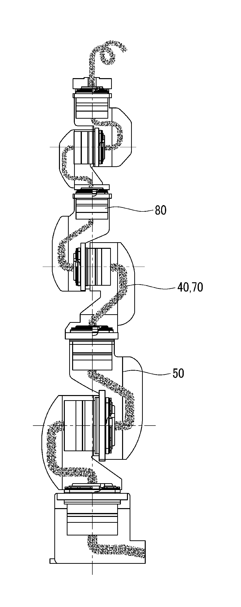
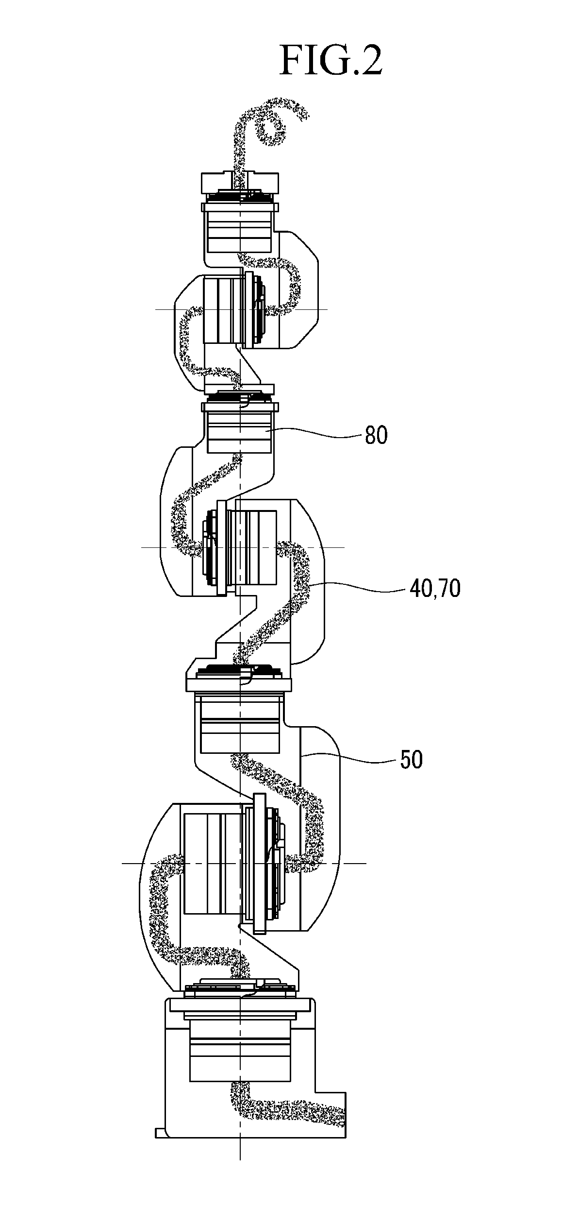
[0088]With reference to FIGS. 7 to 11, the hollow driving module of the present invention generally includes a hollow motor 210, a decelerator 220, a first driving link 261, a first encoder 240, and a second encoder 250, a link connection means 231.

[0089]Hereinafter, a detailed description of the same configuration will be omitted.

[0090]The torque transmission unit 237 is connected with the output side of the decelerator 220 to be rotatable, and an outer side of the torque sensor 230 is connected with an outer rim of a cross roller bearing 271 to be supported, and is connected with the decelerator 220 through the torque transmission unit 237 to measure torque transmitted from the output side of the decelerator 220.

[0091]An outer side of the torque sensor 230 is connected with an outer rim of a cross roller bearing 271 to be supported, and is connected with ...

exemplary embodiment 3

[0112]Exemplary embodiment 3 relates to an exemplary embodiment of an operation of the hollow driving module 1 of the present invention.

[0113]With reference to FIGS. 13 and 14, the hollow driving module of the present invention generally includes a hollow motor 310, a decelerator 320, a torque transmission unit 337, a blocking bearing 336.

[0114]Hereinafter, a detailed description of the same configuration will be omitted.

[0115]The torque transmission unit 337 is connected with the output side of the decelerator 320 to be rotatable, and an outer side of the torque sensor 330 is connected with an outer rim of a cross roller bearing 371 to be supported, and is connected with the decelerator 320 through the torque transmission unit 337 to measure torque transmitted from the output side of the decelerator 320.

[0116]In the meantime, the decelerator 320 may be a harmonic decelerator. A detailed description of the decelerator 320 will be omitted.

[0117]An inner rim of the blocking bearing 33...


PUM


Abstract

The present invention relates to a hollow driving module comprising a hollow driving module including a hollow motor including a stator, a rotor rotating with respect to the stator and having a perforated center portion, and a rotation shaft disposed at and coupled to the perforated center portion of the rotor; a decelerator connected with the rotation shaft positioned at an output side of the hollow motor to decelerate rotation of the rotation shaft; a torque transmission unit being connected to an output side of the decelerator to be driven by a decelerated rotation angle; a first encoder positioned at an input side opposite to a side connected with the decelerator of the hollow motor; a second encoder positioned at a side opposite to a side connected with the hollow motor of the first encoder; and a link connection means connecting the second encoder with the torque transmission unit.

Description

CROSS-REFERENCE TO RELATED APPLICATION[0001]This application claims priority to and the benefit of Korean Patent Application Nos. 10-2012-0033089, 10-2012-0032907, 10-2012-0032940 filed in the Korean Intellectual Property Office on Mar. 30, 2012, the entire contents of which are incorporated herein by reference.BACKGROUND OF THE INVENTION[0002](a) Field of the Invention[0003]The present invention relates to a hollow driving module.[0004](b) Description of the Related Art[0005]In general, an industrial robot configures a joint with a solid decelerator, a servo motor, and a brake, and controls a position or a speed by receiving feedback of the position and the speed by using a solid rotation angle sensor 30 of a shaft 20 of the servo motor 10 as illustrated in FIG. 1. However, in this case, a power line 40 and a sensor line of the servo motor 10 are exposed outside of a robot main body 50.[0006]In a manufacturing business field using a robot, lightness and simplification of a robot ha...

Claims


Application Information

Patent Timeline
Patent Type & Authority Applications(United States)
IPC IPC(8): H02K7/00H02K7/116H02K11/00
CPCH02K7/003H02K7/116H02K11/0042H02K11/0015H02K11/21H02K11/24
Inventor PARK, CHAN HUNKYUNG, JIN-HOCHOI, TAE YONGDO, HYUN MINPARK, DONG II
Owner KOREA INST OF MACHINERY & MATERIALS
Why Eureka
Try Eureka