Method And Apparatus For The Determination Of Laser Correcting Tool Parameters

Active Publication Date: 2012-04-05
CARL ZEISS SMS GMBH
View PDF2 Cites 19 Cited by
  • Summary
  • Abstract
  • Description
  • Claims
  • Application Information

AI Technical Summary

Benefits of technology

[0034]This aspect of the inventive principle is beneficial in that it does not require additional measurements in order to determine the at least one unknown laser beam parameter. In order to be able to correct registration errors, they have to be known, and thus they have to be measured. After the error correction is performed, it is at least from time

Problems solved by technology

As a consequence, the manufacturing of photolithographic masks with increasing resolution is becoming more and more complex, and thus more and more expensive as well.
However, this approach requires some efforts.
It is a major d

Method used


Image

  • Method And Apparatus For The Determination Of Laser Correcting Tool Parameters
  • Method And Apparatus For The Determination Of Laser Correcting Tool Parameters
  • Method And Apparatus For The Determination Of Laser Correcting Tool Parameters

Examples


Embodiment Construction

[0052]This part of the specification refers to part 6 entitled “theoretical background” of the U.S. provisional application U.S. 61 / 363,352. Equations of this part are used in this application without further explanation. Some of the problems of photolithographic masks and of templates for the nanoimprint lithography are also briefly discussed in the above mentioned document.

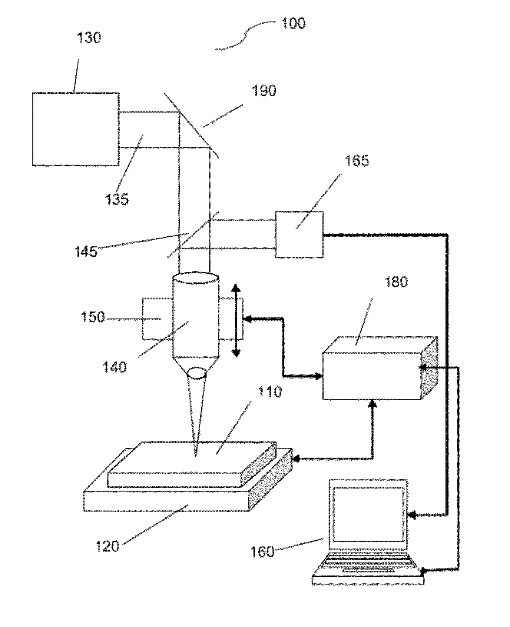
[0053]This section begins with a brief description of the apparatus used for the correction of deficits of transparent materials. In the second part, two alternative approaches are presented to determine the at least one unknown laser beam parameter.

[0054]In the following, the present invention will be more fully described hereinafter with reference to the accompanying Figures, in which exemplary embodiments of the invention are illustrated. However, the present invention may be embodied in different forms and should not be construed as limited to the embodiments set forth herein. Rather, these embodiments are p...


PUM


Abstract

The invention relates to a method for determining at least one unknown laser beam parameter of a laser beam used for correcting errors of a transparent material including inducing a first persistent modification in the material by an interaction with the laser beam having a first set of laser beam parameters, measuring the induced first persistent modification of the material, calculating a second persistent modification in the material using a model describing persistent modifications in the material with a second set of laser beam parameters, wherein the first set of laser beam parameters comprises the second set of laser beam parameters and the at least one unknown laser beam parameter, setting up a target functional including the first persistent modification and the second persistent modification, and determining the at least one unknown laser beam parameter by minimizing the target functional.

Description

CROSS REFERENCE TO RELATED APPLICATIONS[0001]Pursuant to 35 U.S.C. §119, this application claims the benefit of U.S. provisional application 61 / 389,382, filed on Oct. 4, 2010, which is herein incorporated by reference.FIELD OF THE INVENTION[0002]The present invention relates to the field of the determination of laser correcting tool parameters.BACKGROUND OF THE INVENTION[0003]As a result of the constantly increasing integration density in the semiconductor industry, photolithographic masks or templates of the nanoimprint lithography have to project smaller and smaller structures onto a photosensitive layer, i.e., a photoresist dispensed on wafers. In order to fulfil this demand, the exposure wavelength of photolithographic masks has been shifted from the near ultraviolet across the mean ultraviolet into the far ultraviolet region of the electromagnetic spectrum. Presently, a wavelength of 193 nm is typically used for the exposure of the photoresist on wafers. As a consequence, the m...

Claims


Application Information

Patent Timeline
IPC IPC(8): G06F15/00
CPCB82Y10/00B82Y40/00H01S3/0014G03F1/72G03F7/0002G03F1/60
Inventor DMITRIEV, VLADIMIR
Owner CARL ZEISS SMS GMBH
Why Eureka
Try Eureka