

Optical imaging system with aberration correcting means
Patent Information
- Authority / Receiving Office
- US · United States
- Current Assignee / Owner
- IND RES LTD
- Publication Date
- 2004-12-09
- Estimated Expiration
- Not applicable · inactive patent
Smart Images
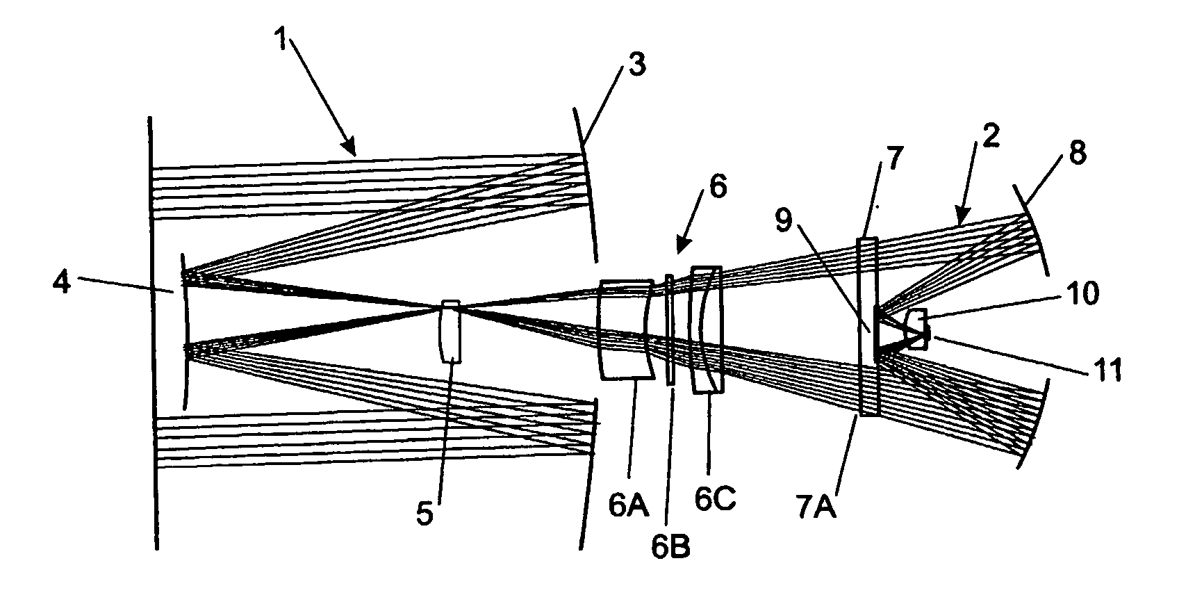
Figure 1 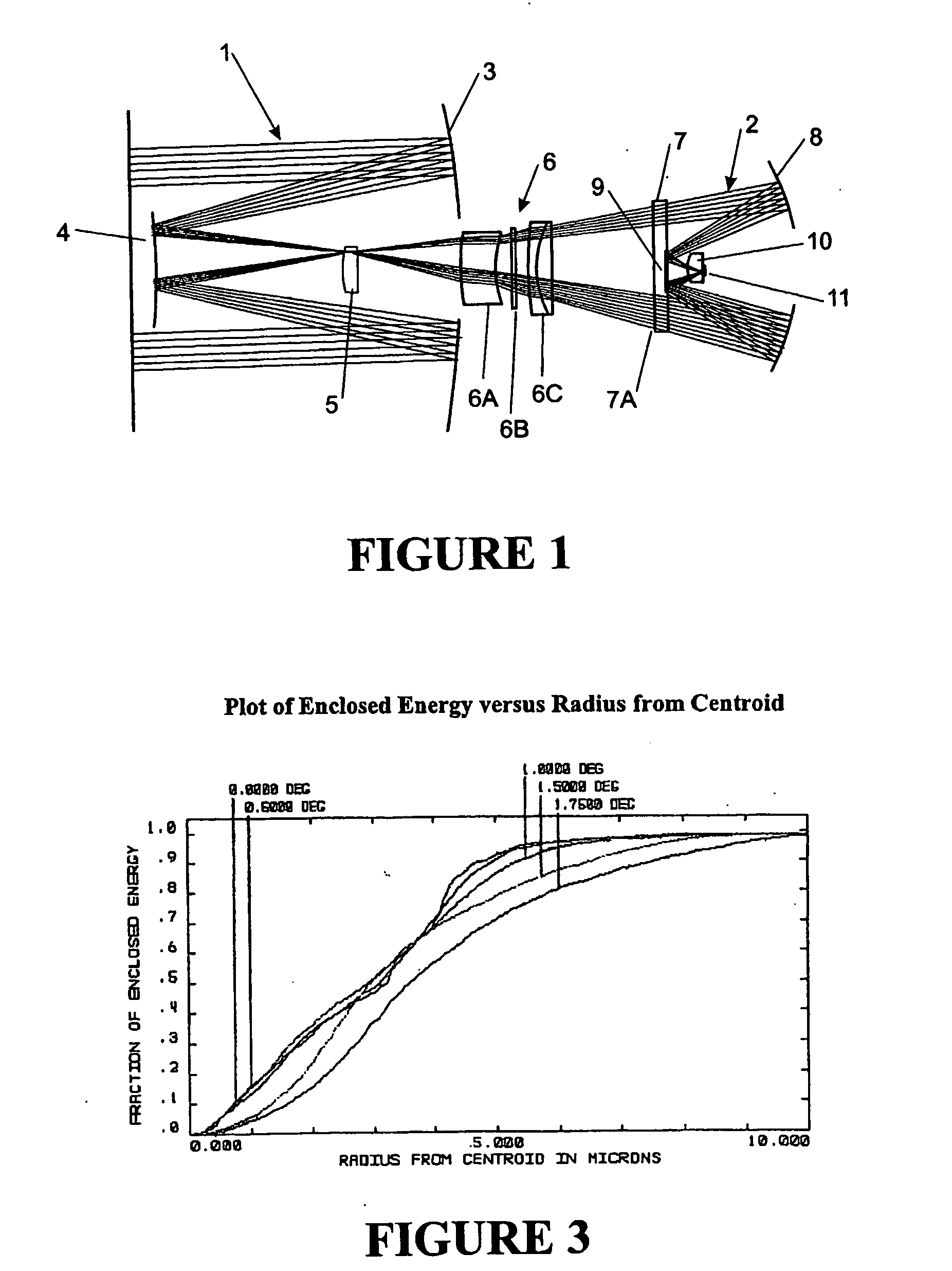
Figure 2 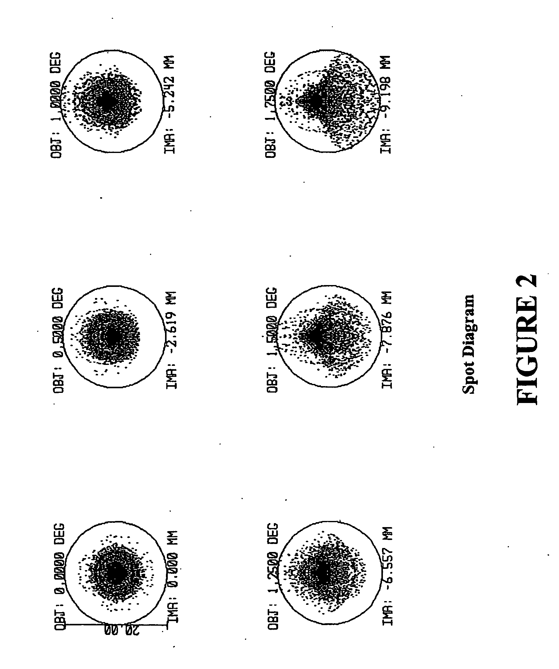
Figure 3
Abstract
Description
[0001] The present invention relates to an optical imaging system and in particular, but not exclusively, to an optical imaging system suitable for use in low light level imaging.
[0002] Imaging performance of an optical imaging system can be expressed as some combination of the following parameters:
[0003] Numerical Aperture (N.A.) or "speed"--for low-light-level capability;
[0004] Field angle--for the biggest picture;
[0005] Angular resolution--for the sharpest picture;
[0006] Spectral bandpass--for multi-spectral capability;
[0007] Pupil diameter--for the highest (appropriate) upper limit of light-gathering power; and
[0008] Transmission losses.
[0009] The planar nature of solid-state imaging devices dictates the need for flat-field imaging optics; hence, a further desirable characteristic is a flat focal surface.
[0010] Also, the limited lateral dimensions of solid state imaging devices relative to those of photographic emulsion substrates, require shorter focal lengths in order to achie...