Maintaining PEM fuel cell performance with sub-freezing boot strap starts

a fuel cell and subfreezing technology, applied in the direction of fuel cell details, fuel cell control, electrochemical generators, etc., can solve the problems of unacceptably poor performance of the end plate, pronounced only slightly improved performance at the cathode end of the cell stack assembly, so as to avoid performance loss, mitigate or eliminate performance loss, and improve end-cell performance

Inactive Publication Date: 2004-12-09
INT FUEL CELLS
View PDF6 Cites 20 Cited by
  • Summary
  • Abstract
  • Description
  • Claims
  • Application Information

AI Technical Summary

Benefits of technology

0005] This invention is predicated on our discovery that poor end-cell performance in a fuel cell stack assembly following boot strap startup at sub-freezing temperatures is due to the end plates, which typically comprise a very large heat sink, and cool the end cells to temperatures below the water freezing point, which is unacceptable unless some form of performance recovery is implemented. The invention is predicated in part on our discovery that heating of the end cells at the cathode end of the cell stack assembly can mitigate or eliminate the performance loss. The invention is also predicated in part on our discovery that heating of the end cells or of the adjacent end plate can avoid loss of performance resulting from boot strap startup at sub-freezing temperatures.

Problems solved by technology

When proton exchange membrane (PEM) fuel cells are started at sub-freezing temperatures, either directly with the intended load, such as electric vehicle powered by such cell, or by means of an auxiliary load, or both, the cells adjacent to the end plates (current collectors, or pressure plates) exhibit unacceptably poor performance, which is especially pronounced in the cells close to the cathode end of the cell stack assembly.
But performance at the cathode end of the cell stack assembly improves only slightly and never recovers completely by itself.
Although it has been shown that the performance loss was caused by cathode flooding which may be mitigated or even cured completely by dry-out or by hydrogen pump, both of these procedures are too complicated for satisfactory use by users, particularly with respect to a fuel cell powering an electric vehicle.
In the prior art, the problem was different since all of the individual cells were brought up to proper operating temperature before startup, by circulation of preheated coolant through the stack.
In a fuel cell operating a vehicle at sub-freezing temperatures, the delay of 15 minutes (or more) to achieve cell operating temperature would be intolerable.

Method used


Image

  • Maintaining PEM fuel cell performance with sub-freezing boot strap starts
  • Maintaining PEM fuel cell performance with sub-freezing boot strap starts
  • Maintaining PEM fuel cell performance with sub-freezing boot strap starts

Examples


first embodiment

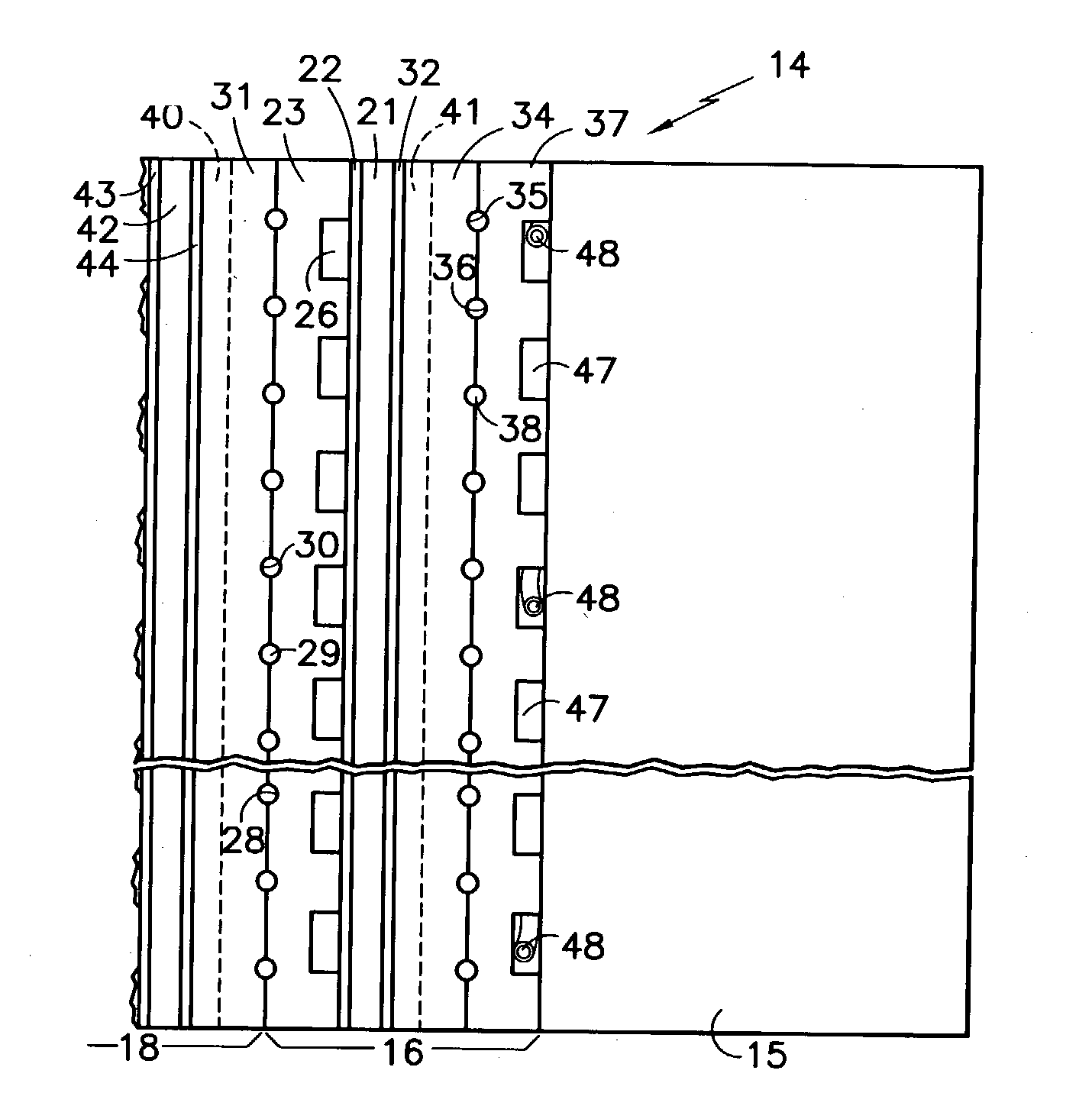
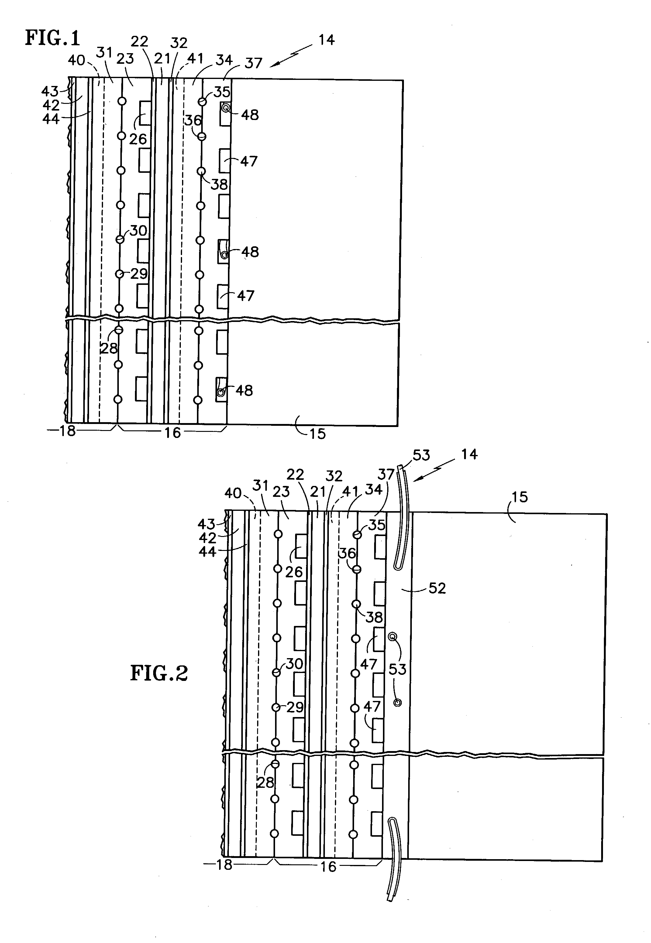
[0020] The next-to-end fuel cell 18, only partially shown, includes a membrane electrode assembly 42, an anode support plate 43, and a cathode support plate 44, the remainder of this fuel cell being broken away for simplicity. The additional anode water transport plate 37, which is present simply to complete the water passages 38 for the cathode of the last fuel cell 16 does not have any fuel reactant gas flowing in channels 47. In the invention, insulated resistance wire 48 may be threaded through some, as shown, or all, of the channels 47, as necessary, to provide sufficient heat so that the end fuel cell 16 will not be below freezing temperatures during a boot strap startup, or to provide sufficient heat so as to cause recovery of the end cell 16, as the case may be.

second embodiment

[0021] In the invention shown in FIG. 2, a heater plate 52 has insulated resistance wire 53 embedded therein and is disposed between the additional water transport plate 37 and the end plate 15. The wire 53 may be in a zig-zag or serpentine path or in any other suitable shape as may be found desirable in any particular utilization of the present invention.

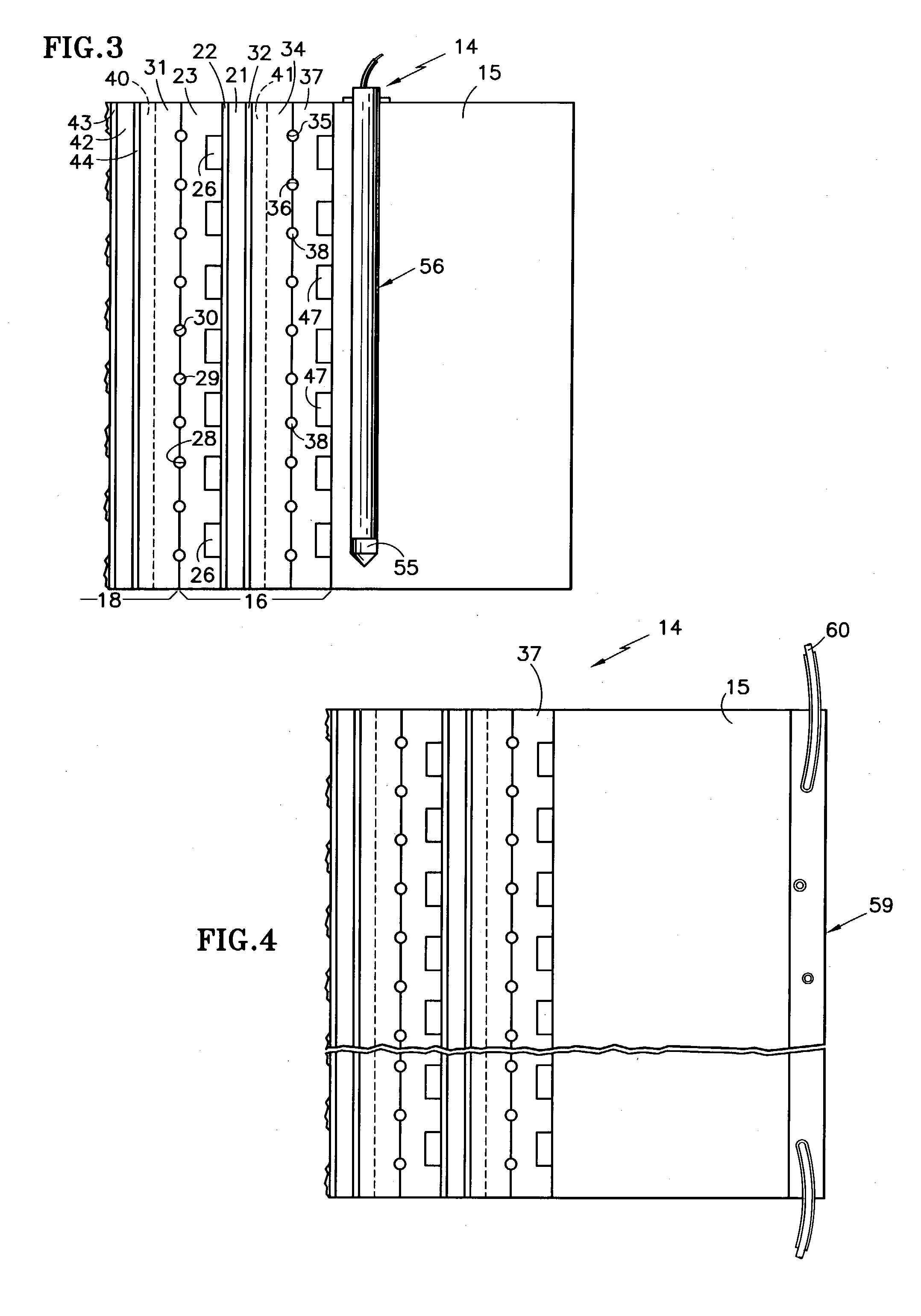
[0022] In FIG. 3, the end plate 15 has a plurality of holes 55 drilled therein (only one being shown) and a heater 56 disposed in each of the holes. Preferably, the heater 56 is disposed close to that surface of the end plate 15 which is in contact with the additional water transport plate 37. However, the heaters could be in other positions.

[0023] The embodiments of FIGS. 1-3 serve not only to heat the fuel cell itself, either directly or through conduction, but also to provide a temperature gradient which isolates the fuel cell from most or all of the cold mass of the end plate 15.

[0024] In FIG. 4, an electric heater element 59 h...


PUM

PropertyMeasurementUnit
temperatureaaaaaaaaaa
insulated resistanceaaaaaaaaaa
electric resistanceaaaaaaaaaa

Abstract

The fuel cells (16, 18) adjacent or near the end plate (15) of a fuel cell stack (14) are warmed either by (a) a heater wire (48) within the fuel cell (16) adjacent to the end plate, (b) heater wires (53) are disposed in a heater element (52) located between the end plate and the fuel cell closest to the end plate (15), (c) one or more heaters (56) are disposed in holes (55) within the end plate (15), (d) electric heating elements (59) on a surface of the end plate (15), or (e) a catalytic heater (61) disposed on the surface of the end plate. The fuel cells (16, 18) may be heated before or during operation at sub-freezing temperatures to prevent loss of fuel cell performance, or may be heated after operation at sub-freezing temperatures to restore fuel cell performance.

Description

[0001] This invention relates to utilizing heat at or near the end cell and / or adjacent pressure plate (also known as end plate or current collector) in PEM fuel cells which are started at sub-freezing temperatures, to avoid cells with degraded performance and / or to restore cell performance.[0002] When proton exchange membrane (PEM) fuel cells are started at sub-freezing temperatures, either directly with the intended load, such as electric vehicle powered by such cell, or by means of an auxiliary load, or both, the cells adjacent to the end plates (current collectors, or pressure plates) exhibit unacceptably poor performance, which is especially pronounced in the cells close to the cathode end of the cell stack assembly.[0003] Over a period of time, the cells located at the anode end of the cell stack recover just by running the fuel cell. But performance at the cathode end of the cell stack assembly improves only slightly and never recovers completely by itself. Although it has be...

Claims


Application Information

Patent Timeline
Patent Type & Authority Applications(United States)
IPC IPC(8): H01M8/02H01M8/04
CPCH01M8/0202H01M8/04007H01M8/04022H01M8/04223Y02E60/50H01M8/04302H01M8/04225H01M8/0267H01M8/043
Inventor RESNICK, GENNADYREISER, CARL A.POPOVICH, NEIL A.YI, JUNG S.
Owner INT FUEL CELLS
Why Eureka
Try Eureka