Annular combustion chamber for a gas turbine

a gas turbine and combustion chamber technology, applied in the direction of machines/engines, efficient propulsion technologies, lighting and heating apparatus, etc., can solve the problems of unnecessari cooling of hot working gas, inconvenient operation, and inability to be leak-proof, etc., to achieve simple and low leakage

Inactive Publication Date: 2004-12-16
SIEMENS AG
View PDF85 Cites 22 Cited by
  • Summary
  • Abstract
  • Description
  • Claims
  • Application Information

AI Technical Summary

Benefits of technology

[0014] above, which is simple in structure and suitable for the liner of a closed air cooling system.
[0036] It is also proposed with the invention that the first row of turbine vanes be connected in a fixed manner to the annular combustion chamber. In turbines with a standard structure the first row of vanes is linked to a vane carrier and suspended in a floating manner, as large movement differentials due to heat occur at this point. The inventive integration of the first row of vanes into the annular combustion chamber means that the large movement differentials due to heat are avoided at this point. The two significant hot components--the liner and ring with the first row of turbine vanes--are therefore only connected at one axial fixing point to the cold annular combustion chamber housing. The complete assembly is also supported on the spatially bound shaft guard.

Problems solved by technology

These elements can move in a free manner thermally but have the disadvantage of being "non-leaktight".
The cooling air escapes through the many gaps directly into the hot gas without any benefit--on the contrary the hot working gas is unnecessarily cooled ("open cooling" with the disadvantages mentioned above).

Method used


Image

  • Annular combustion chamber for a gas turbine
  • Annular combustion chamber for a gas turbine
  • Annular combustion chamber for a gas turbine

Examples


Embodiment Construction

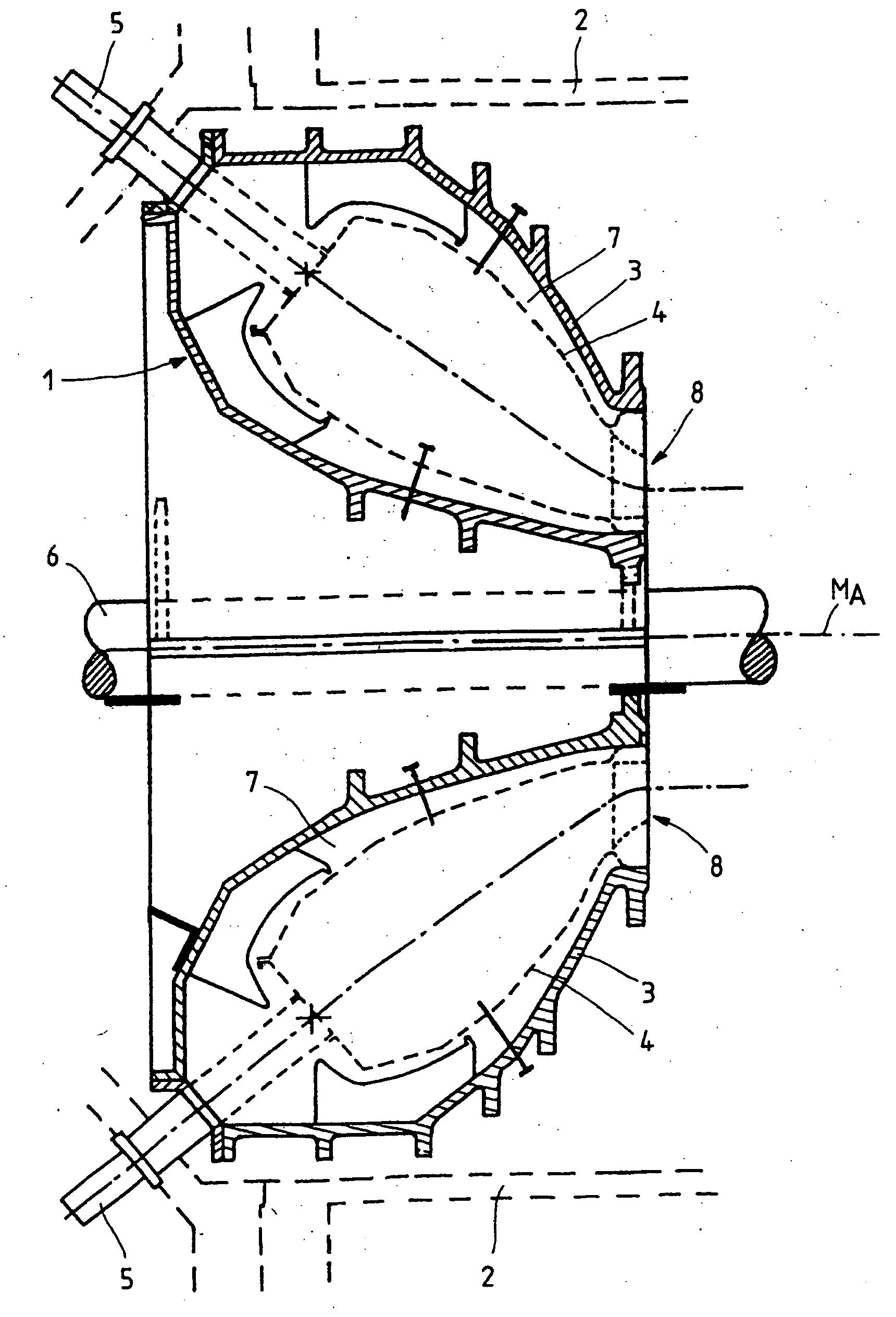
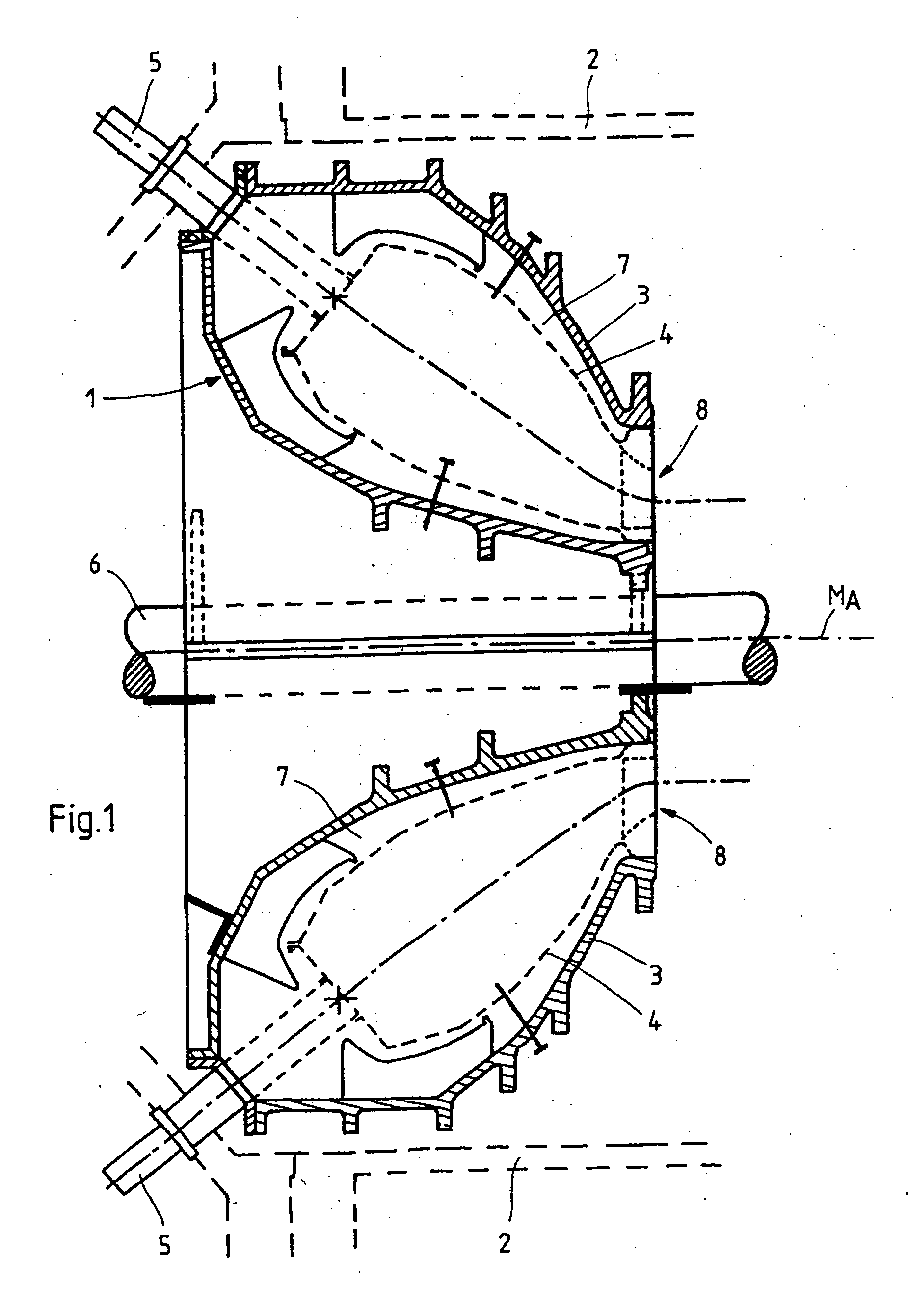
[0046] The Figures are not to scale and only serve for explanatory purposes. The same elements have the same reference characters in the Figures.

[0047] FIG. 1 shows a schematic representation of a longitudinal cross-section through an inventive annular combustion chamber 1 and its position in relation to further components of the turbine.

[0048] The annular combustion chamber housing 1,3 is supported on the spatially bound shaft guard 53 and is linked to the pressure-resistant outer housing 2; the annular combustion chamber housing is in three parts: it comprises the inner hub housing 1, the outer external shell housing 3 and the connecting burner housing 33. The liner is located in the "torus" formed by the elements 1,3,33 and comprises the outer liner 41 and the inner liner 4. All the housing components are partitioned axially across a sub-joint flange. An annular chamber 7 extending outwards, in which the cooling air is collected and fed to the burners 5, is left between the annul...


PUM


Abstract

An annular combustion chamber for a gas turbine is disclosed, which permits a sealed air cooling, such that high powers and efficiencies can be achieved with low NOx emissions. The two-piece annular combustion chamber housing surrounds a thin-walled sealed liner, which guides the hot gas escaping from the burners to the turbine inlet in a gas-tight manner. A variable annular chamber is located between the liner and the annular combustion chamber housing, in which the cooling air is collected as a counter-current to the hot gas and fed to the burners (closed air cooling). The surfaces of the liner are variably cooled with efficient baffle cooling devices and drilled patterns in. The thermally-elastic liner constructed from submerged arc-welded rings is axially fixed at the flange only and for the remainder provided with reinforcing circumferential beading. The freely expanding liner is otherwise concentrically fixed to the cold annular combustion chamber housing by means of elastic tensioning elements. The above efficient, economical and simple construction further offers significant service advantages due to the following construction features: the burners can be completely (dis)assembled from outside without opening the housing. Both the liner and also a ring which integrates the first row of turbine guide vanes in the annular combustion chamber can be removed as service pieces in other words exchanged without opening the turbine and compressor housing and without removal of a rotor.

Description

[0001] This application is the US National Stage of International Application No. PCT / EP02 / 12448, filed Nov. 7, 2002 and claims the benefit thereof. The International Application claims the benefits of European application No.01127137.6 EP filed Nov. 15, 2001, both of the applications are incorporated by reference herein in their entirety.[0002] The invention relates to an annular combustion chamber for a gas turbine with at least one inlet opening for a burner and an outlet opening into a turbine chamber. The invention further relates to a gas turbine with such an annular combustion chamber.BACKGROUND OF INVENTION[0003] As well as being used to generate a feed force, for example in aircraft, gas turbines are also used extensively in generating plant technology. A fuel / air mixture is ignited and burned in the combustion chamber. The resulting hot combustion gases thereby expand towards a turbine chamber downstream from the combustion chamber, where they encounter an arrangement of v...

Claims


Application Information

Patent Timeline
Patent Type & Authority Applications(United States)
IPC IPC(8): F23R3/42F23R3/00F23R3/50F23R3/60
CPCF23R3/002F23R3/50F23R3/60Y02T50/67Y02T50/60
Inventor LIEBE, ROLAND
Owner SIEMENS AG
Why Eureka
Try Eureka