Video snychronisation

a video stream and video technology, applied in the field of video synchronisation, can solve the problems of different paths taken by video streams through the network to be subject to different delays, and not tru

Active Publication Date: 2004-12-23
SONY EUROPE BV
View PDF10 Cites 33 Cited by
  • Summary
  • Abstract
  • Description
  • Claims
  • Application Information

AI Technical Summary

Problems solved by technology

However an asynchronous network does not inherently maintain frame synchronisation and different paths taken by

Method used


Image

  • Video snychronisation
  • Video snychronisation
  • Video snychronisation

Examples


second example

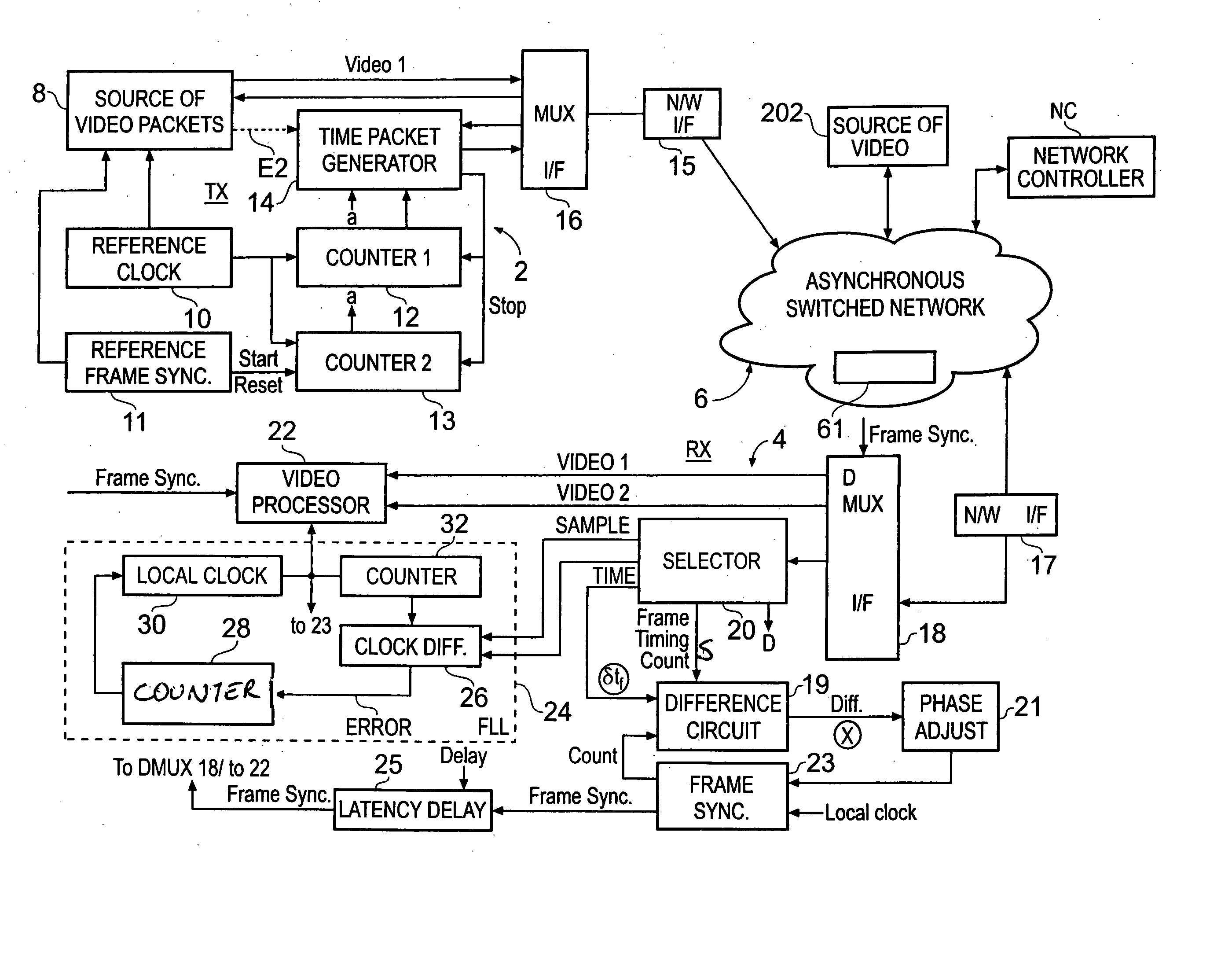
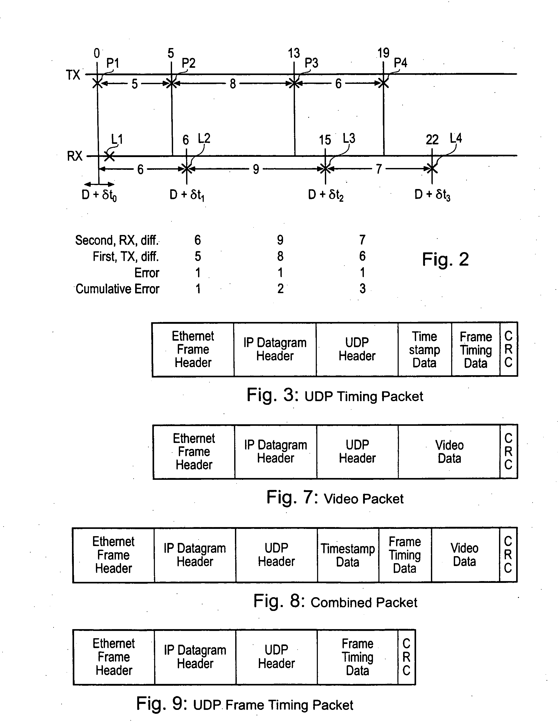
[0088] In contrast to the first example, in the second example, the timestamp data and the frame timing data and the video data may be combined in one packet with common (broadcast) address data.

[0089] Such a packet is shown schematically in FIG. 8. The packet includes headers as described with reference to FIG. 3 or 7. The packet includes data which identifies it as a combined time and video packet. That data may be included in one or more of the headers in known manner. The time stamp data field which contains a small amount of data precedes the video data field which contains a much greater amount of data. A video sequence is transmitted using many packets. The time data may be included in only some, but not all, of the packets. The time data may be included in a combined video packet at frequent, but varying, intervals at times when the network has spare capacity as described above.

[0090] Referring to FIG. 1, the combined video and timing packet is generated in the source 8 but ...

third example

[0091] Referring to FIG. 9, the frame timing data may be placed in a packet which contains only an Ethernet frame header, followed in order by an IP datagram header, a UDP header, frame timing data which is the count .delta.t.sub.f and a CRC. The time stamp data which is the reference count mentioned above is sent in a separate packet (not shown) comprising an Ethernet frame header, followed in order by an IP datagram header, a UDP header, the time stamp data and a CRC.

[0092] Modifications

[0093] In an example described above, one timing packet is produced which contains a single measurement of the value .delta.t.sub.f which is used to control the local frame synchronisation signal generator 23.

[0094] Referring to FIG. 11, in a modification, the average of several measurements of the value .delta.t.sub.f is used to control the local generator 23. The second counter 13 operates to produce a first value of .delta.t.sub.f at a packet transmission time as described above. One or more sub...


PUM


Abstract

A method of synchronising the phase of a local image synchronisation signal generator of a local video data processor in communication with an asynchronous switched packet network to the phase of a reference image synchronisation signal generator of a reference video data processor also coupled to the network, the local and reference processors having respective clocks, the reference and local image synchronisation signal generators generating periodic image synchronisation signals in synchronism with the reference and local clocks respectively comprises the steps of: frequency synchronising the local and reference clocks; the reference video data processor sending, via the network, to the local data processor an image timing packet providing reference image synchronisation data indicating the difference in timing, measured with respect to the reference processor's clock, between the time at which the image timing packet is launched onto the network and the time of production of a reference image synchronisation signal; and the local processor controlling the timing of the production of the local image synchronisation signal in dependence on the reference image synchronisation data and the time of arrival of the timing packet.

Description

[0001] 1. Field of the Invention[0002] The present invention relates to video synchronisation.[0003] 2. Description of the Prior Art[0004] It has been proposed to distribute video data over an asynchronous switched network. The data may be distributed to many receivers which process the data independently of one another. Some processes at the receivers require two video streams to be processed synchronously, for example a simple cut between two video streams must be accurate to one frame boundary. However an asynchronous network does not inherently maintain frame synchronisation and different paths taken by the video streams through the network may be subject to different delays.[0005] A prior proposal, demonstrated at the NAB 2001 conference, distributed video data over a network. Timing data linking local clocks to a reference clock was distributed over another, separate, network[0006] ITU-T Rec H222.0 (1995E) discloses that within the ITU-T Rec H222.01 ISO / IEC 13818-1 systems dat...

Claims


Application Information

Patent Timeline
IPC IPC(8): H04L7/00H04N21/43
CPCH04N21/4305
Inventor COMPTON, MATTHEWGILLARD, CLIVE HENRY
Owner SONY EUROPE BV
Why Eureka
Try Eureka