Phase controller

a controller and phase technology, applied in the direction of electric variable regulation, process and machine control, instruments, etc., can solve the problems of high frequency noise (150 khz to 30 mhz), acoustic noise further occurring, reactance element l generating acoustic noise and/or hea

Active Publication Date: 2004-12-30
MATSUSHITA ELECTRIC WORKS LTD
View PDF7 Cites 24 Cited by
  • Summary
  • Abstract
  • Description
  • Claims
  • Application Information

AI Technical Summary

Problems solved by technology

Especially, a value of di / dt of the TRIAC Q1 at the turning on thereof is much larger, so that high frequency noise (150 kHz to 30 MHz) occurs.
Furthermore, a filament of the incandescent lamp LA is vibrated due to the precipitous load current, so that acoustic noise further occurs.
Furthermore, the reactance element L generates acoustic noise and / or heat.
Thus, the phase controller becomes costly corresponding to upsizing the switching device.

Method used


Image

  • Phase controller
  • Phase controller
  • Phase controller

Examples


first embodiment

[0053] First Embodiment

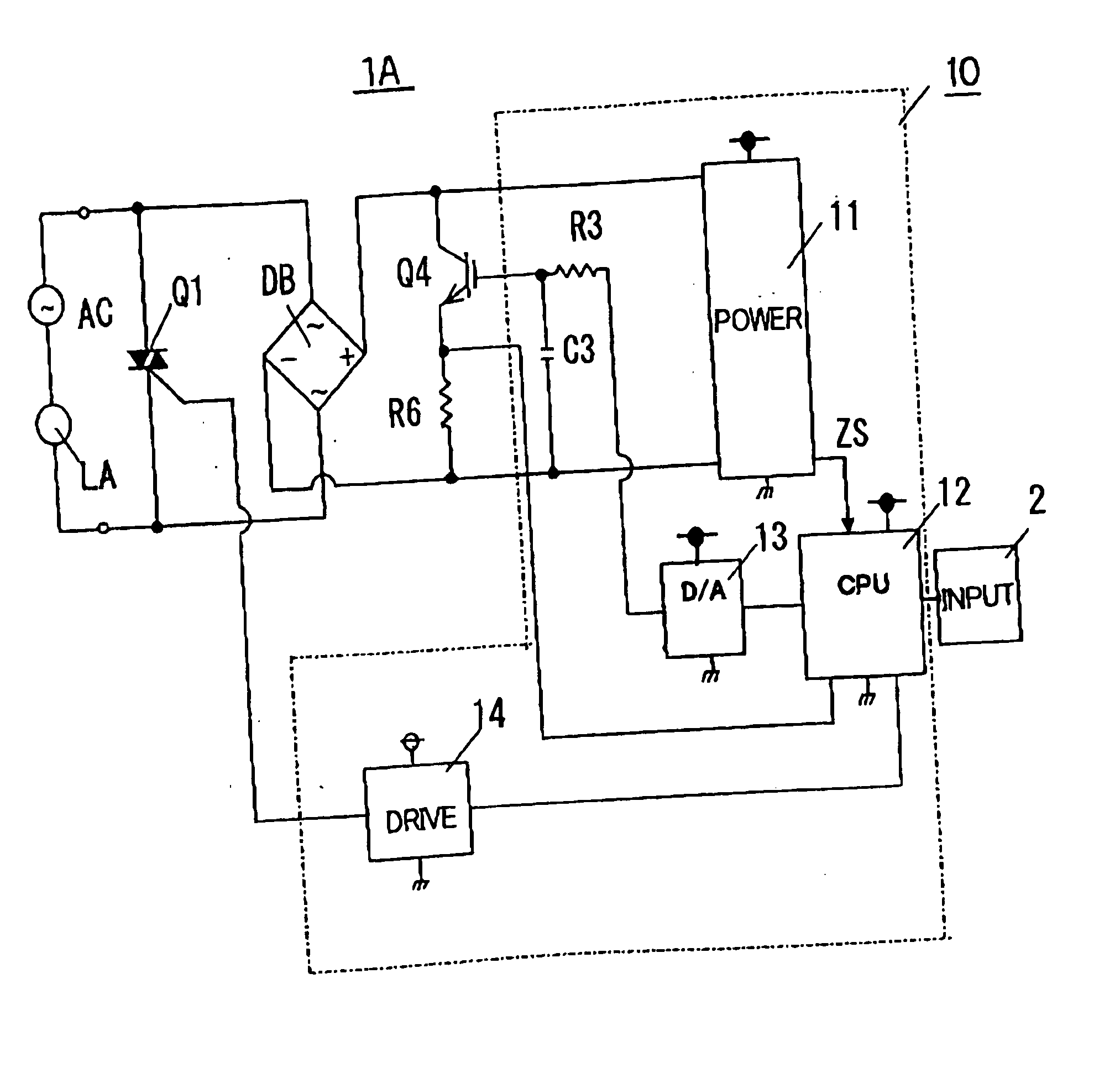
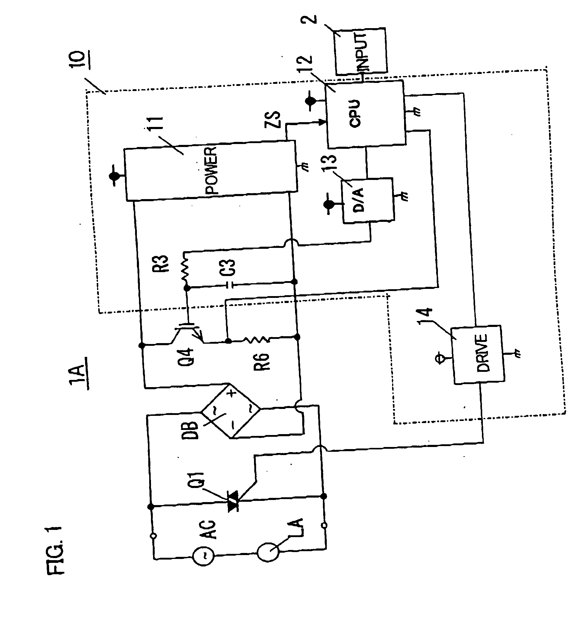
[0054] A circuit diagram of a phase controller 1A in accordance with a first embodiment of the present invention is described with reference to FIG. 1.

[0055] The phase controller 1A comprises a TRIAC Q1 serving as a first switching device, an IGBT Q4 serving as a self-quenching type second switching device, a shunt resistor R6 for sensing a current value flowing in the IGBT Q4, a control circuit 10 for controlling the TRIAC Q1 and the IGBT Q4, and an external input device 2 which is used for setting a luminance ratio (or level of light control) of an incandescent lamp LA. A series circuit of the IGBT Q4 and the shunt resistor R6 is connected between both terminals of the TRIAC Q1 via a diode bridge DB. The phase controller 1A is connected between a terminal of a commercial power source AC and a terminal of the incandescent lamp LA.

[0056] In FIG. 1, a symbol C3 designates a capacitance in a gate of the IGBT Q4 serving as a control terminal, and a symbol R3 desi...

second embodiment

[0099] Second Embodiment

[0100] A phase controller 1B in accordance with a second embodiment of the present invention is described with reference to FIG. 15.

[0101] The phase controller 1B comprises a TRIAC Q1 serving as a first switching device, an IGBT Q2 serving as a self-quenching type second switching device, an IGBT Q3 serving as a self-quenching type third switching device, a first diode D1, a second diode D2, a control circuit 10 for controlling the TRIAC Q1, the IGBT Q2 and the IGBT Q3, and an external input device 2. The IGBT Q2 and the IGBT Q3 are connected in series between both terminals of the TRIAC Q1 in a manner so that turning on direction of the IGBT Q2 is opposite to that of the IGBT Q3. The first diode D1 is connected back-to-back with the terminals of the IGBT Q3 serving as the third switching device. The second diode D2 is connected back-to-back with the terminals of the IGBT Q2 serving as the second switching device. Hereupon, the back-to-back connection is defi...

third embodiment

[0119] Third Embodiment

[0120] A phase controller 1C in accordance with a third embodiment of the present invention is described with reference to FIG. 17.

[0121] The phase controller 1C comprises a TRIAC Q1 serving as a first switching device, an IGBT Q4 serving as a fourth self-quenching type switching device connected between both terminals of the TRIAC Q1 via a diode bridge DB, an IGBT Q2 serving as a self-quenching type second switching device, an IGBT Q3 serving as a self-quenching type third switching device, a control circuit 10 for controlling the TRIAC Q1, the IGBT Q2, the IGBT Q3 and the IGBT Q4, and an external input device 2. The IGBT Q2 and the IGBT Q3 are connected in series between both terminals of the TRIAC Q1 in a manner so that turning on direction of the IGBT Q2 is opposite to that of the IGBT Q3. A gate of the IGBT Q2 and a gate of the IGBT Q3 are respectively connected to a D / A converting circuit 13 of the control circuit 10 via a resistor R4. The IGBT Q2, the I...


PUM


Abstract

In a phase controller used in a light control of an incandescent lamp, noise reduction, prevention of elements from damage due to short circuit current, downsizing and lower cost are purposed. A CPU circuit of a control circuit sets a gradual increase term during which a load voltage applied to the incandescent lamp is gradually increased by driving a self-quenching type switching device such as an IGBT. After passing the gradual increase term, a main switching device such as a TRIAC is turned on. The phase controller further comprises a current sensor such as a shunt resistor for sensing a value of the load current flowing through the self-quenching type switching device, according to need. The CPU circuit compares the sensed value of the load current with at least one reference value, and selects driving manner of the main switching device and the self-quenching type switching device corresponding to the result of comparison.

Description

[0001] 1. Field of the Invention[0002] The present invention relates to a phase controller used as a light controller of an incandescent lamp.[0003] 2. Description of the Related Art[0004] A phase controller using a bilateral thyristor (hereinafter called TRIAC) is conventionally used as a light controller of an incandescent lamp. Circuit diagrams of typical phase controllers are shown in FIGS. 22A to 22C.[0005] The phase controller has two terminals respectively connected between both terminals of a series circuit of a commercial power source AC and a load such as an incandescent lamp LA. As shown in FIG. 22A, a TRIAC Q1 is connected in parallel with the series circuit of the commercial power source AC and the incandescent lamp LA. A trigger circuit T is configured by a damping time circuit which is a series circuit of a resistor R.sub.1, a variable resistor R2 and a capacitor C.sub.1, a DIAC Q5 connected between a connection point of the capacitor C1 and the variable resistor R2 a...

Claims


Application Information

Patent Timeline
Patent Type & Authority Applications(United States)
IPC IPC(8): H05B39/04H05B39/08
CPCH05B39/048H05B39/08Y02B20/148Y02B20/00
Inventor MUKAI, TATSUYAKITAMURA, NOBUHIROMURATA, YUKIHIROOKADA, KENJI
Owner MATSUSHITA ELECTRIC WORKS LTD
Why Eureka
Try Eureka