Method and apparatus for coloring electric wire

Inactive Publication Date: 2004-12-30
YAZAKI CORP
View PDF10 Cites 0 Cited by
  • Summary
  • Abstract
  • Description
  • Claims
  • Application Information

AI Technical Summary

Benefits of technology

[0036] According to the present invention described above, the outer surface of the wire is colored with the heated coloring agent. Therefore, the coloring agent adhering to the outer surface of the electric wire is quickly dried. Further, since the coloring agent is heated up to a range lower than the boiling point of the solvent of the coloring agent, said solvent is hard to evaporate.
[0043] According to the present invention as described above, the outer surface of the electric wire is colored with the heated coloring agent. Therefore, the coloring agent adhering to the outer surface of the wire is quickly dried. Further, the heater heats the receiver. Therefore, the nozzle is not heated and the coloring agent is reliably kept at a range lower than the boiling point of the solvent. Therefore, the coloring agent is hard to evaporate.
[0045] According to the present invention as described above, since the cooling means cools the nozzle, the temperature of the coloring agent is reliably kept at a range lower than the boiling point of the solvent.

Problems solved by technology

That is, whenever the color of the wire is changed, it is necessary to halt an operation of an extrusion apparatus causing increasing in a time period and labor hour required for the production of the wire and deteriorating in the productivity of the wire.
In such a case, right after changing the color of the coloring agent, a wire, in the color of the synthetic resin of which a coloring agent before the replacement and a coloring agent after the replacement are mixed, has been inevitably manufactured, causing the deterioration in the yield of the material of the wire.
This is, of course, undesirable, because the outer surface of the wire is contaminated.
At worst, the wires may be hard to be identified.
Further, since the coloring agent is heated up to a range lower than the boiling point of the solvent of the coloring agent, said solvent is hard to evaporate.
Therefore, the coloring agent is hard to evaporate.

Method used


Image

  • Method and apparatus for coloring electric wire
  • Method and apparatus for coloring electric wire
  • Method and apparatus for coloring electric wire

Examples


Embodiment Construction

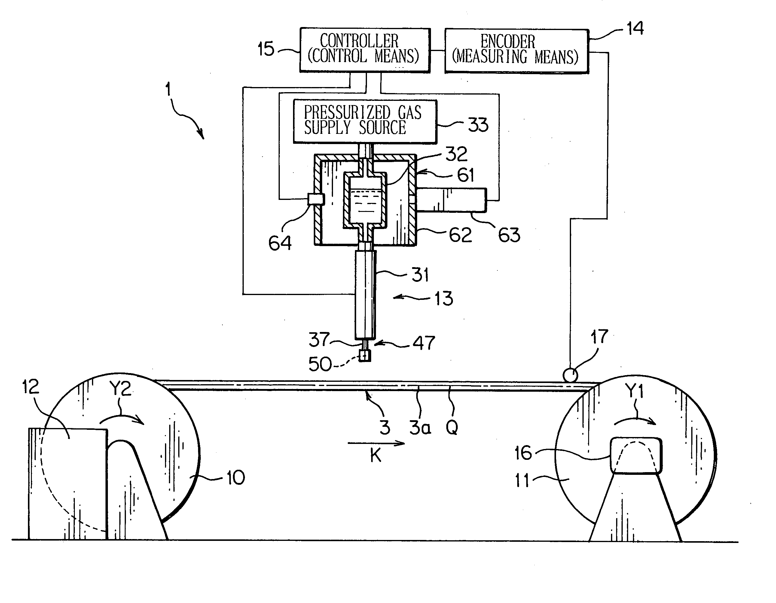
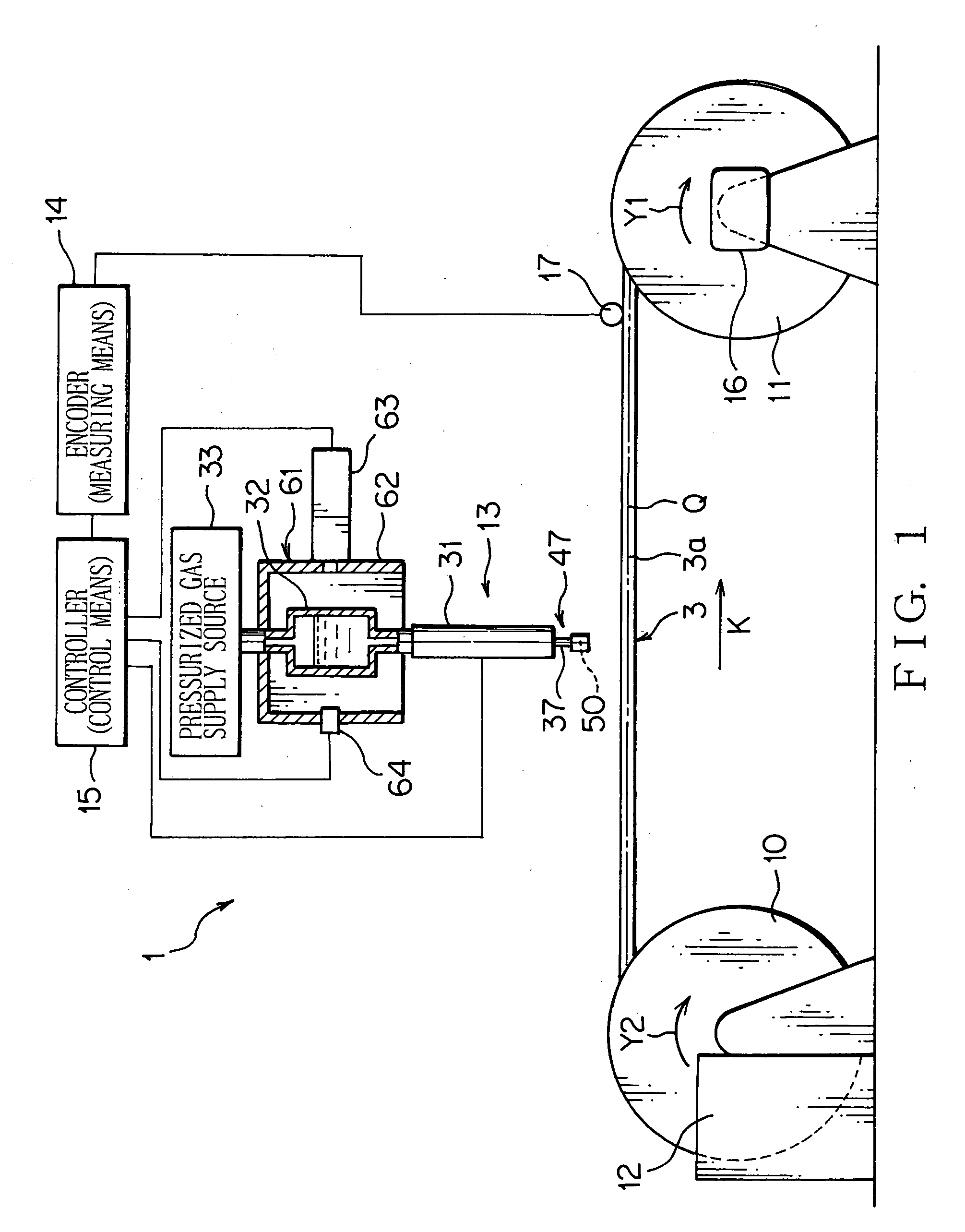
[0051] In the following, an apparatus 1 for coloring an electric wire (hereinafter referred to as a coloring apparatus 1) according to a first preferred embodiment of the present invention will be explained with reference to FIGS. 1-3. The coloring apparatus 1 shown in FIG. 1 and so on is an apparatus for forming a mark 6 on a part of an outer surface 3a of an electric wire 3 (i.e. wire 3). That is, the coloring apparatus 1 colors the outer surface 3a of the wire 3, i.e. performs marking on the outer surface 3a of the wire 3.

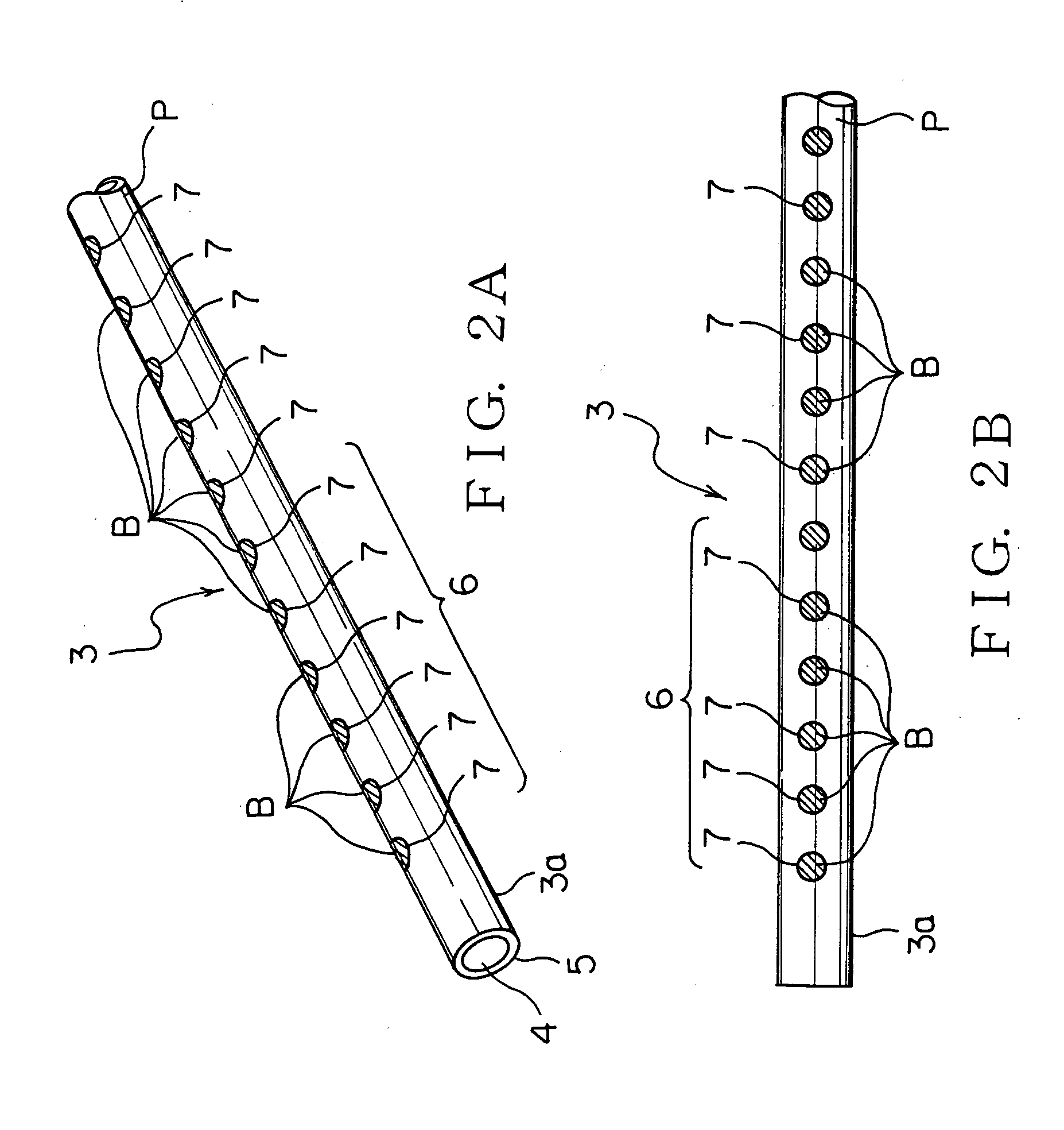
[0052] An electric wire 3 constitutes a wiring harness to be mounted on a motor vehicle or the like as a mobile unit. As shown in FIG. 2A and so on, the wire 3 includes an electrically conductive core wire 4 and an electrically insulating coating 5. A plurality of element wires are bundled up to form the core wire 4. Each element wire of the core wire 4 is made of electrically conductive metal. The core wire 4 may be constituted by a single element wire. The coa...


PUM

PropertyMeasurementUnit
Temperatureaaaaaaaaaa
Timeaaaaaaaaaa
Boiling pointaaaaaaaaaa

Abstract

A coloring apparatus for coloring an electric wire colors the wire spouts a liquid coloring agent, including a coloring material and a solvent, toward an outer surface of the wire with a specific amount thereof at a time. The coloring apparatus includes a coloring agent supply source for receiving the coloring agent, a coloring nozzle and a heater. The coloring nozzle spouts the coloring agent of the coloring agent supply source. The heater includes a heating bath and a hot air inlet. The heating bath receives the coloring nozzle. The heating bath allows the coloring nozzle to spout the coloring agent. The hot air inlet supplies hot air into the heating bath to heat the coloring agent supply source. The heater heats the coloring agent to a range lower than a boiling point of the solvent by the hot air inlet supplying the hot air into the heating bath.

Description

[0001] The priority application Number Japanese Patent Application No. 2003-179717 upon which this patent application is based is hereby incorporated by reference.[0002] The present invention relates to a method and an apparatus for coloring an electric wire that includes an electrically conductive core wire and an electrically insulating coating for coating the core wire.DESCRIPTION OF THE RELATED ART[0003] Various electronic devices are mounted on a motor vehicle as a mobile unit. Therefore, the motor vehicle is provided with a wiring harness for transmitting power from a power source and control signals from a computer to the electronic devices. The wiring harness includes a plurality of electric wires and connectors attached to an end of the wires.[0004] The wire includes an electrically conductive core wire and a coating made of insulating synthetic resin, which coats the core wire. The wire is a so-called coated wire. A connector includes a terminal fitting and a connector hou...

Claims


Application Information

Patent Timeline
IPC IPC(8): B05D3/02B05C5/00B05D7/20H01B13/34
CPCH01B13/345
Inventor KAMATA, TAKESHISUGIMURA, KEIGOSAITO, SEIYAGI, KIYOSHI
Owner YAZAKI CORP
Why Eureka
Try Eureka