Knock detecting apparatus for internal combustion engine

Active Publication Date: 2005-01-06
50 TO TOYOTA JIDOSHA KK +1
View PDF22 Cites 32 Cited by
  • Summary
  • Abstract
  • Description
  • Claims
  • Application Information

AI Technical Summary

Benefits of technology

[0007] An object of the present invention is to provide a knock detecting appara

Problems solved by technology

However, the frequency band generated by the engine knock is not always the same.
However, in such a knock determination, when multiple noises are su

Method used


Image

  • Knock detecting apparatus for internal combustion engine
  • Knock detecting apparatus for internal combustion engine
  • Knock detecting apparatus for internal combustion engine

Examples


Embodiment Construction

[0018] An embodiment of the present invention will be described hereinafter with reference to the drawings.

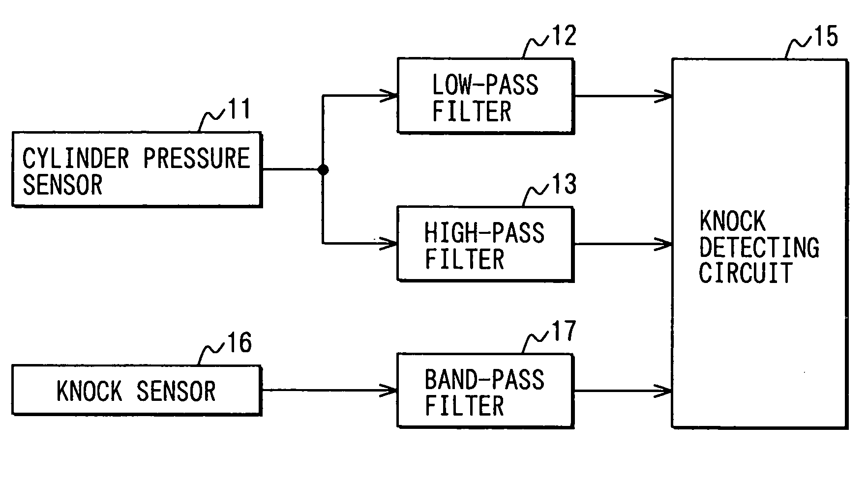
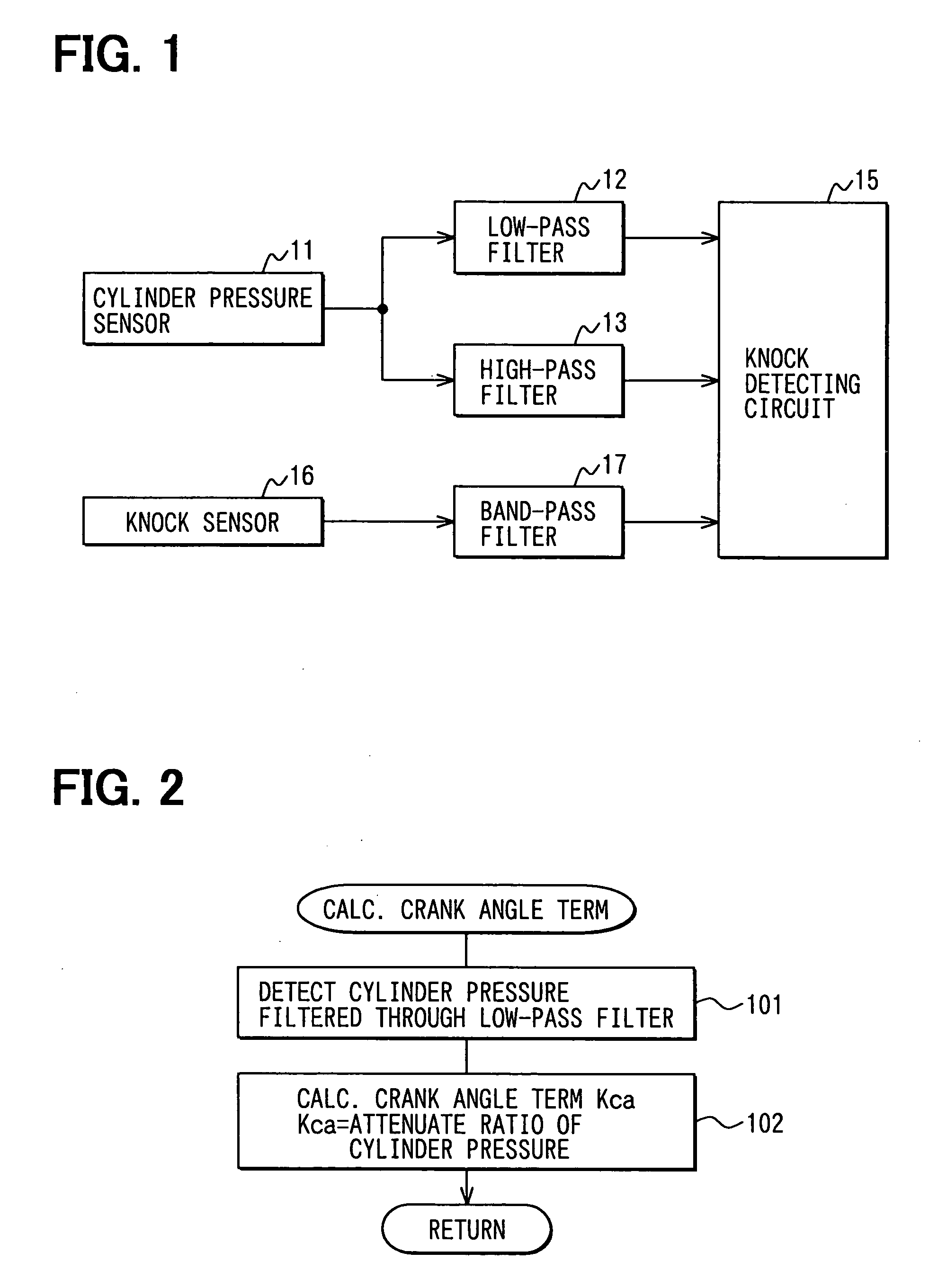
[0019]FIG. 1 shows a system of a knock detecting apparatus mounted on a vehicle. A cylinder pressure sensor 11 is disposed at a predetermined cylinder. The cylinder pressure sensor 11 outputs a waveform signal indicative of a condition of combustion. The sensor 11 can be of a type integrated with a spark plug or can be of a type having a sensing portion toward a combustion chamber. A low-pass filter 12 and a high-pass filter 13 receive the waveform signal and output the signal to a knock detecting circuit 15.

[0020] The signal from the cylinder pressure sensor 11 includes a signal indicative of a change of a piston movement and a change of cylinder pressure, and also includes a high-frequency noise. The low-pass filter 12 removes the high-frequency noise, which is noise of 100 to 1000 Hz, in order to detect pressure changes in the cylinder precisely.

[0021] The high-pass filte...


PUM


Abstract

A waveform knock signal detected by a knock sensor is filtered through a band-pass filter. The detected wave form signal is compared with an ideal reference knock waveform to determine an engine knock. The ideal reference knock waveform is derived on the basis of a factor depending on a crank angle, a factor depending on a real time and a factor depending on an engine construction. The factor depending on the real time is calculated based on an energy loss in a combustion chamber and a time constant of the band-pass filter. The factor depending on the engine construction is calculated based on a knock vibration which is generated in a cylinder, transferred to a cylinder block and detected by the knock sensor.

Description

CROSS REFERENCE TO RELATED APPLICATION [0001] This application is based on Japanese Patent Application No. 2003-270560 filed on Jul. 3, 2003, the disclosure of which is incorporated herein by reference. FIELD OF THE INVENTION [0002] The present invention relates to a knock detecting apparatus for an internal combustion engine. BACKGROUND OF THE INVENTION [0003] A knock detecting apparatus, as shown in JP-6-60621B, has a knock sensor disposed on a cylinder block of an engine. The knock sensor detects a knock vibration and outputs a knock signal. Knock frequency components corresponding to the engine knock are derived from the knock signal by a band-pass filter. A peak value of the knock frequency components is detected by a peak-hold circuit, and then the peak value is compared with a knock determining level to determine a presence or absence of the engine knock. Alternately, the knock frequency components in a predetermined range are integrated, and the integrated value is compared ...

Claims


Application Information

Patent Timeline
IPC IPC(8): F02D45/00G01H17/00G01L23/22G01M15/00
CPCG01L23/225
Inventor TAKEMURA, YUICHIINOUE, MASAOMI
Owner 50 TO TOYOTA JIDOSHA KK
Why Eureka
Try Eureka