
Filter assembly with slip thread

Active Publication Date: 2005-01-06
PARKER INTANGIBLES LLC
View PDF14 Cites 55 Cited by
  • Summary
  • Abstract
  • Description
  • Claims
  • Application Information

AI Technical Summary

Benefits of technology

[0013] The present invention thereby provides a novel and unique filter assembly including a replaceable element and a cover which can temporarily retain the element, whereby the cover and element have cooperating structure to prevent the cover from being attached to the housing without an element present, and which is simple and relatively inexpensive to manufacture.
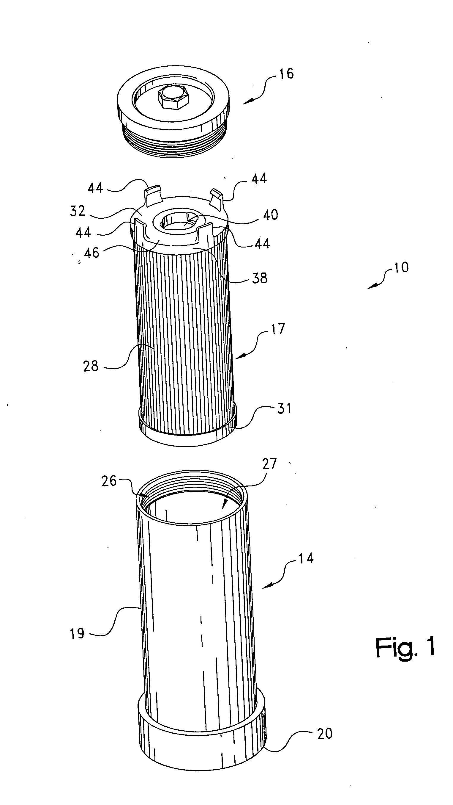
[0015] According to a preferred embodiment, the cover includes a circular body portion, and an annular sleeve integral with and projecting axially away from a surface of the body portion from an inner, attached end to an outer, distal end. The sleeve has a series of distinct recesses in an outer surface thereof, with the recesses spaced around the circumference of the sleeve and dimensioned and located to receive the fingers on the end cap of the filter element. The collar member surrounds the sleeve and is retained by a snap ring to the cover for free rotation relative thereto. The collar member includes i) a threaded portion on an outer surface thereof to allow the cover to be screwed onto and off of the housing, and ii) a series of recesses in an inner surface thereof opening to an outer end of the collar member. The collar member is rotatable into a position relative to the sleeve such that the recesses in the sleeve can be radially aligned with and oppositely positioned relative to the recesses in the collar member such that the fingers of the filter element can be inserted therebetween.
[0018] When the element is spent and is to be replaced, the cover is screwed off of the open end of the housing and the filter element is removed along with the cover. As the cover is unscrewed from the housing, the collar rotates into a position where the collar locks the filter element to the cover, that is, the collar member rotates relative to the sleeve such that the cam surfaces enclose the catches in their respective recesses and prevent the fingers from being removed from the cover. This prevents the element from becoming detached from the cover as the fluid-laden element is removed from the housing. To remove the element from the cover, the collar is rotated slightly with respect to the cover member such that the recesses in the sleeve and collar again become aligned, and the fingers can then be removed from the recesses to separate the filter element from the cover either by pulling out sharply on the element, or raising the collar such that the each catch easily passes over its respective lip.

Problems solved by technology

One disadvantage with replaceable elements is that when the cover is removed, the element can be saturated with liquid, which can get on the user's hands and clothes as the user attempts to grasp an end cap of the element to remove the element from the housing.
Also, it can just be difficult to get one's fingers between the end cap and the housing to grasp the filter element.
Nevertheless, one drawback of such designs is that the cover can be replaced on the housing without an element present.
In other words, there is nothing to prevent the user from simply removing the spent element, and then reattaching the cover on the housing without including a fresh element.
When the fluid system is thereafter operated, non-filtered fluid can pass through the housing and potentially cause issues with downstream components in the system.
Unfortunately not all filter applications can have such a valve assembly incorporated into the housing.
Also, such a valve assembly has a number of parts, which can increase the cost of the assembly.
While this design prevents the use of the assembly without an element being present, the element is not retained on a cover, and must be directly handled when it is desired to remove the element form the housing.

Method used


Image

  • Filter assembly with slip thread
  • Filter assembly with slip thread
  • Filter assembly with slip thread

Examples


Embodiment Construction

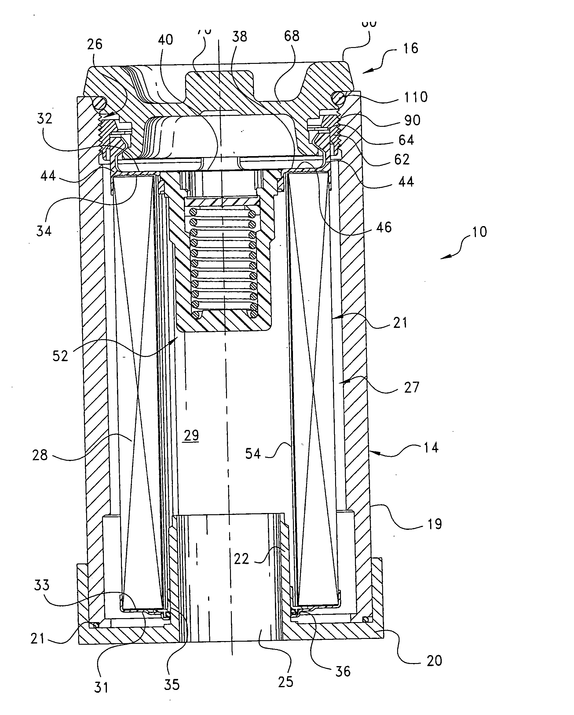
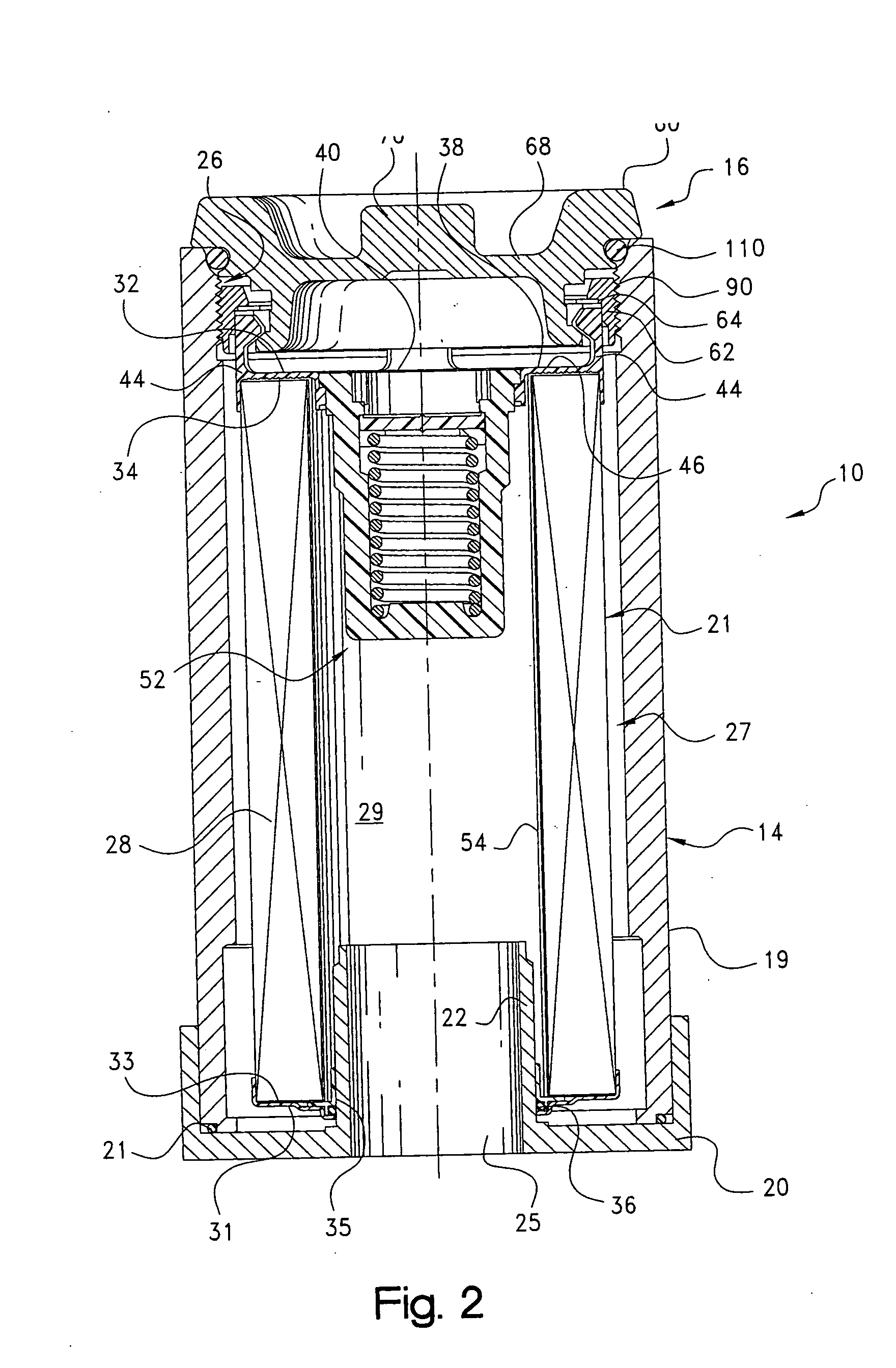
[0030] Referring to the drawings, and initially to FIGS. 1 and 2, a filter assembly constructed according to the principles of the present invention is indicated generally at 10. The filter assembly 10 includes a filter element, indicated generally at 12; a housing, indicated generally at 14; and a cover assembly, indicated generally at 16. As should be appreciated upon reviewing the following description, the filter assembly is useful for filtering a variety of fluids, for example hydraulic fluid.

[0031] The housing 14 for the filter element generally comprises an elongated canister having a cylindrical body portion 19 and an annular head assembly 20, which is retained to one end of the body portion such as by threads. An O-ring seal or other type of gasket 21 (FIG. 2) is provided between head assembly 20 and body portion 19 to provide a fluid-tight seal. Head assembly 20 includes an inwardly-extending collar 22 bounding central opening 25, and defining a first, outlet flow path in...


PUM

PropertyMeasurementUnit
Flexibilityaaaaaaaaaa
Areaaaaaaaaaaa
Distanceaaaaaaaaaa

Abstract

A filter assembly comprising a housing with a threaded open end, a filter element, and a cover assembly. The filter element includes a media ring and a pair of end caps, one of which includes outwardly-projecting fingers. The cover assembly includes a cover member, and a sleeve with recesses in an outer surface. A collar member surrounds the sleeve and is freely rotationally supported by the cover member. The collar member includes i) a threaded portion on an outer surface for screwing the cover member onto the housing, and ii) recesses in an inner surface. The collar member is rotatable relative to the sleeve such that the recesses in the collar member and in the sleeve can be aligned, and the fingers can be inserted therebetween, to rotationally lock the collar member relative to the sleeve and to retain the element with the cover.

Description

CROSS-REFERENCE TO RELATED CASES [0001] The present application claims the benefit of the filing date of U.S. Provisional Application Ser. No. 60 / 484,121; filed Jul. 1, 2003, the disclosure of which is expressly incorporated herein by reference.FIELD OF THE INVENTION [0002] The present invention relates generally to filter assemblies and elements therefore, for removing particulate and other contaminants from a fluid stream. BACKGROUND OF THE INVENTION [0003] Certain filter assemblies include a filter element located in a housing, where a cover encloses the open end of the housing and provides access to the element for replacement when the element becomes used, worn or spent. The cover has threads on an outer surface thereof which engage cooperating threads on the housing to enable the cover to be easily screwed onto and off of the housing. [0004] One known type of filter element for such a filter housing comprises a sheet of filter material folded to form a plurality of parallel pl...

Claims


Application Information

Patent Timeline
IPC IPC(8): B01D29/21B01D35/147
CPCB01D29/21B01D35/147B01D2201/291B01D2201/301B01D2201/4015B01D29/96B01D35/30
Inventor REYNOLDS, ANITA L.GEMBOLIS, DONALD J.HERR, RAYMOND G.MILLER, DANIEL W.
Owner PARKER INTANGIBLES LLC
Learn More