Cross-eye technique implementation

a technology of cross-eye and technique, applied in wave based measurement systems, communication jamming, instruments, etc., can solve problems such as misguided missile launches toward aircraft, and achieve the effect of improving control of amplitude ratio and out of phase condition, and simplifying the implementation of a cross-eye system

Inactive Publication Date: 2005-01-06
EXCELIS INC
View PDF7 Cites 15 Cited by
  • Summary
  • Abstract
  • Description
  • Claims
  • Application Information

AI Technical Summary

Benefits of technology

We have observed that the implementation of a cross-eye system can be simplified in such a way as to improve control of the amplitude ratio and the out of phase condition for the jamming signal in a hostile environment. In accordance wit

Problems solved by technology

When the pair of inverted amplitude signals arrive at the antenna of the fire control radar—the 180 degrees out of phase condition causes wavefront distortion, which further causes the fire control radar to re-align its antenna away from the aircraft.
When the jamming signal reaches the radar antenna, the resulting wavefront distortion (caused by the inverted amplitude components that are 180 degrees out of phase with each other) causes the fire control radar to attempt to track the jamming signal instead of the

Method used


Image

  • Cross-eye technique implementation
  • Cross-eye technique implementation
  • Cross-eye technique implementation

Examples


Embodiment Construction

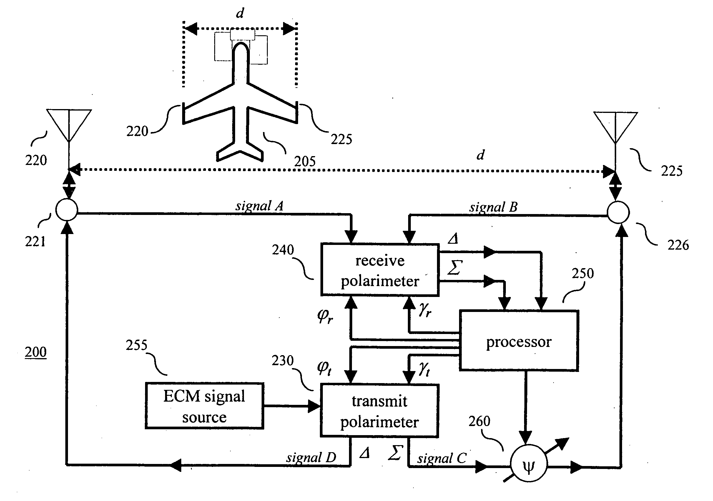
The inventive concept is illustrated in the context of an aircraft comprising an EW cross-eye system for use in jamming a fire control radar (not shown). Other than the inventive concept, the EW cross-eye technique and circuitry for processing microwave signals are well-known and not described further herein. (For example, polarimeters, components based on monolithic microwave integrated circuits (MMICs) and stored-program control processors, e.g., a microprocessor, are well known and not described in detail herein.) In addition, the embodiments described herein are implemented using conventional programming techniques, which, as such, are not described herein.

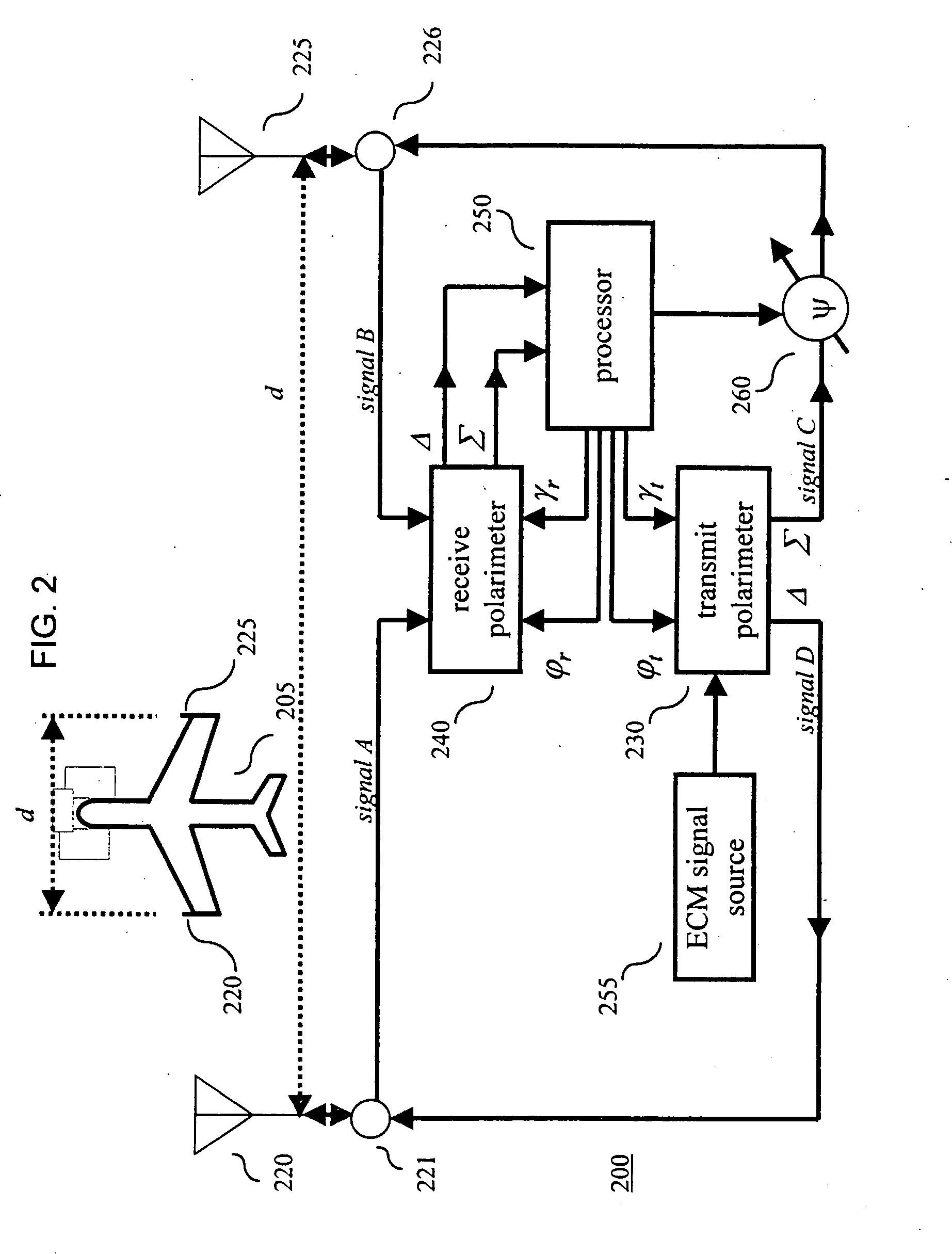
Turning to FIG. 2, an illustrative cross-eye system 200 in accordance with the principles of the invention is shown. Cross-eye system 200 comprises antennas 220 and 225, circulators 221 and 226, a receive polarimeter 240, a transmit polarimeter 230, a processor 250, an electronic counter-measures (ECM) signal source 255 and...


PUM


Abstract

An electronic warfare (EW) cross-eye system comprises two antennas separated a distance, d, a part, where d is much greater than the wavelength, λ, of a tracking signal emitted by a fire control radar (i.e., d >>λ). The EW cross-eye system further comprises a receive polarimeter for measuring the tracking signal and a second polarimeter for synthesizing the measured tracking signal to produce, for transmission, a jamming signal comprising a pair of inverted amplitude signals that are 180 degrees out of phase with each other.

Description

BACKGROUND OF THE INVENTION The invention relates generally to electronic warfare (EW) systems and, more particularly, to devices and techniques for jamming tracking radars. “Cross-eye” jamming is a known technique for masking an object or platform, e.g., an aircraft, from fire control radars. In a cross-eye system, a portion of the signal transmitted by a fire control radar—the threat signal—is received by the aircraft and is processed to form a jamming signal comprising a pair of inverted amplitude signals that have a phase relationship between them that is 180 degrees out of phase. The jamming signal is then transmitted back toward the radar antenna. When the pair of inverted amplitude signals arrive at the antenna of the fire control radar—the 180 degrees out of phase condition causes wavefront distortion, which further causes the fire control radar to re-align its antenna away from the aircraft. This type of cross-eye system 10 is illustrated in FIG. 1. (It should be noted tha...

Claims


Application Information

Patent Timeline
IPC IPC(8): G01S7/02G01S7/282G01S7/38
CPCG01S7/024G01S7/38G01S7/282
Inventor SPARROW, MITCHELL J.CIKALO, JOSEPH
Owner EXCELIS INC
Why Eureka
Try Eureka