Projection type video display

Active Publication Date: 2005-01-06
SANYO ELECTRIC CO LTD
View PDF2 Cites 11 Cited by
  • Summary
  • Abstract
  • Description
  • Claims
  • Application Information

AI Technical Summary

Benefits of technology

[0019] The light at the periphery of the light source is shaded, ther

Problems solved by technology

Since a shading plate in a state where it does not block the projection of a video must be positioned outside an optical path, however, a sliding space

Method used


Image

  • Projection type video display
  • Projection type video display
  • Projection type video display

Examples


Embodiment Construction

[0034] A liquid crystal projector according to an embodiment of the present invention will be described on the basis of FIGS. 1 to 8.

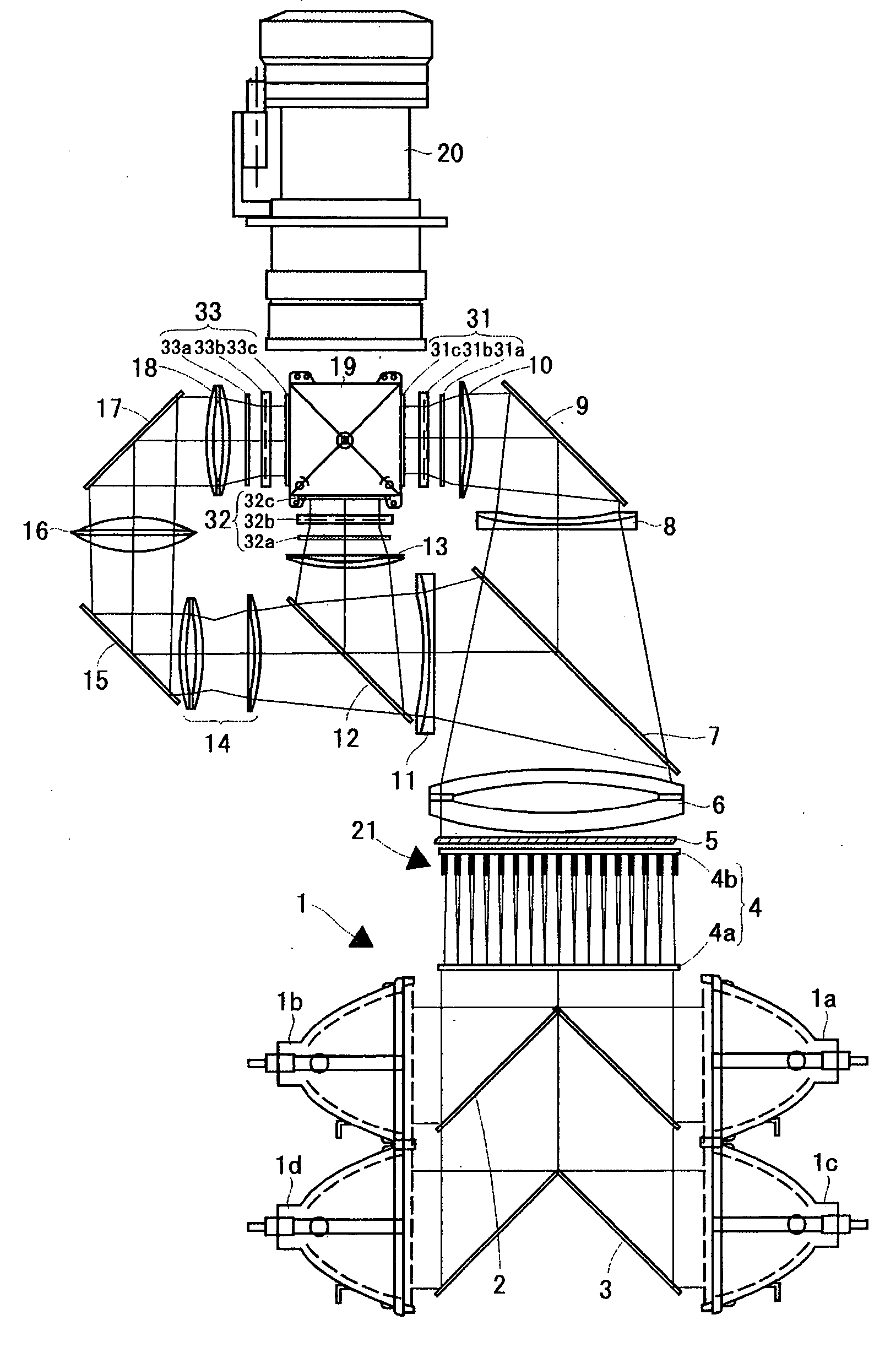
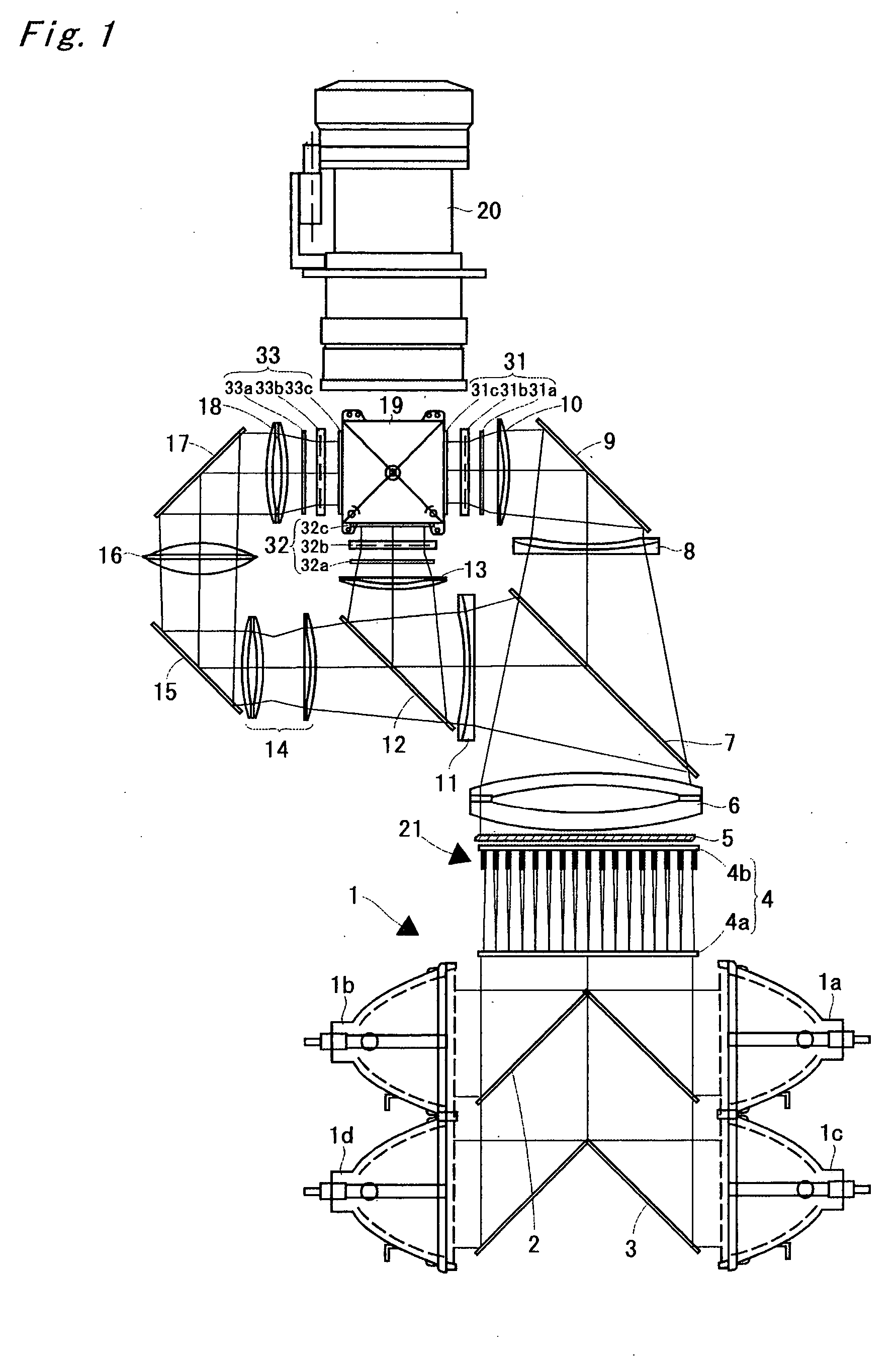
[0035]FIG. 1 is a diagram showing a four-lamp and three-panel liquid crystal projector according to an embodiment of the present invention. An illuminating device 1 comprises four light sources 1a, 1b, 1c, and 1d, a mirror 2 arranged between the light sources 1a and 1b, and a mirror 3 arranged between the light sources 1c and 1d. Each of the light sources is composed of a ultra-high pressure mercury lamp, a metal halide lamp, a xenon lamp, or the like, and its irradiated light is emitted after being changed into parallel lights by a parabolic reflector, to be introduced into an integrator lens 4.

[0036] The integrator lens 4 comprises a pair of fly's eye lenses 4a and 4b. Each of the pair of lenses introduces light emitted from the illuminating device 1 into the whole surface of a liquid crystal light valve, described later, to average partial non-uni...


PUM


Abstract

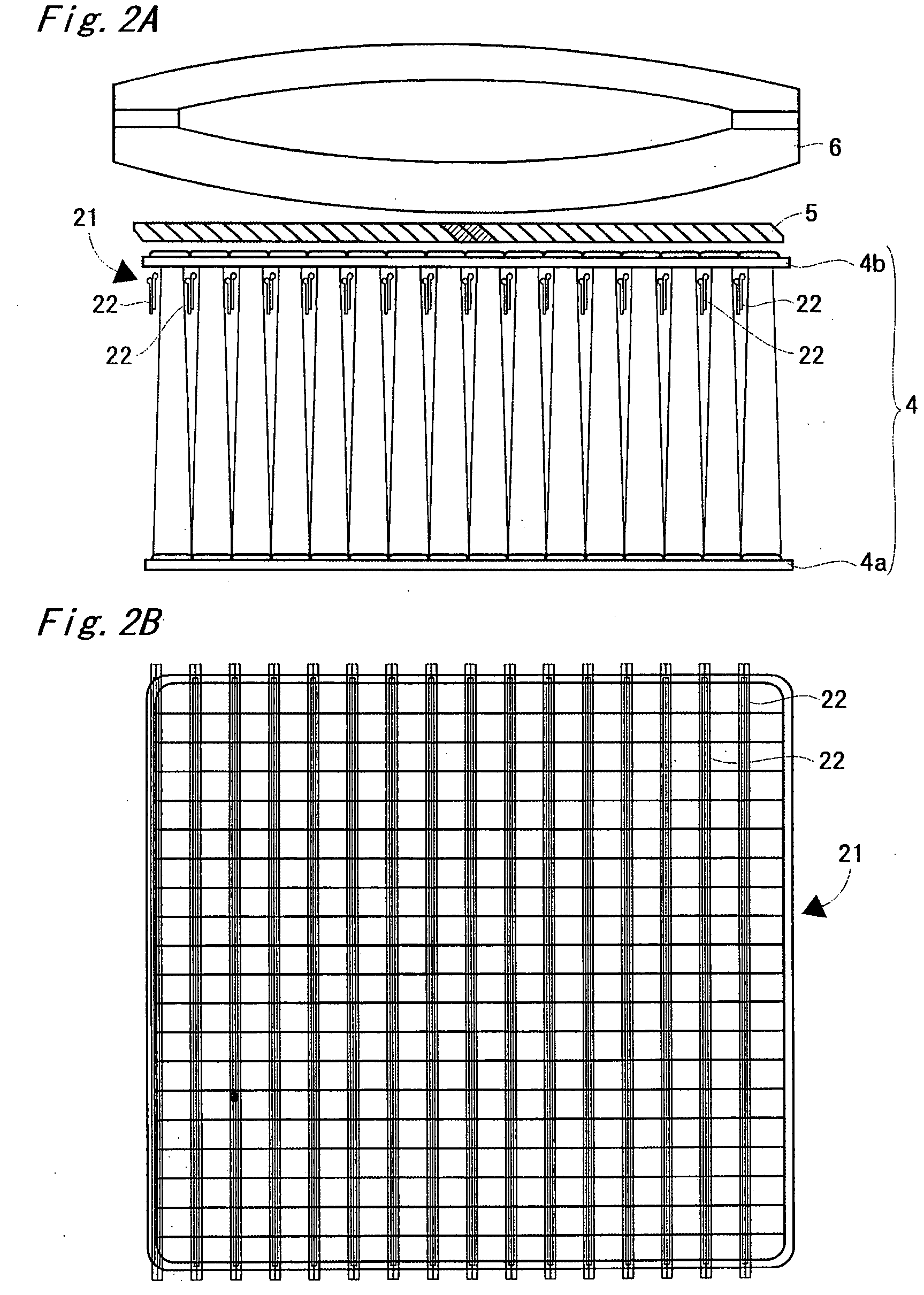
A shutter device comprises a plurality of shutters. Each of the shutters is provided at a position in the vicinity of a fly's eye lens positioned on the side of a polarization conversion system (one of fly's eye lenses in an integrator lens) and not preventing the passage of effective illuminating light. Each of the shutters is constructed as a first shutter or a second shutter. The first shutter is constructed so as to block an upper one-third region and a lower one-third region of the fly's eye lens, and the second shutter is constructed so as to block an intermediate one-third region of the fly's eye lens

Description

BACKGROUND OF THE INVENTION [0001] 1. Field of the Invention [0002] The present invention relates to a projection type video display such as a liquid crystal projector. [0003] 2. Description of the Background Art [0004] As a method of utilizing a liquid crystal projector, a video signal outputted from a personal computer is received, to project a video. That is, when a person who makes a presentation operates a personal computer to display a video which he or she desires to make participants see on a display of the personal computer, the same video as the displayed video is enlarged and projected on a screen by a liquid crystal projector, so that all the participants can see the video. On the other hand, the person who makes a presentation may not, in some cases, desire a video which appears during an operation to be viewed by the participants. In order to cope with such a request, a liquid crystal projector in which a shading plate for temporarily blocking the projection of the vid...

Claims


Application Information

Patent Timeline
IPC IPC(8): G02B27/14G02F1/13G02F1/13357G03B21/00G03B21/14H04N5/74
CPCG02B27/1046G02B27/145H04N9/315H04N9/3141G02B27/149
Inventor KOBA, HIROKI
Owner SANYO ELECTRIC CO LTD
Why Eureka
Try Eureka