
Method and device for detecting land pre-pits

Inactive Publication Date: 2005-01-06
THOMSON LICENSING SA
View PDF2 Cites 4 Cited by
  • Summary
  • Abstract
  • Description
  • Claims
  • Application Information

AI Technical Summary

Benefits of technology

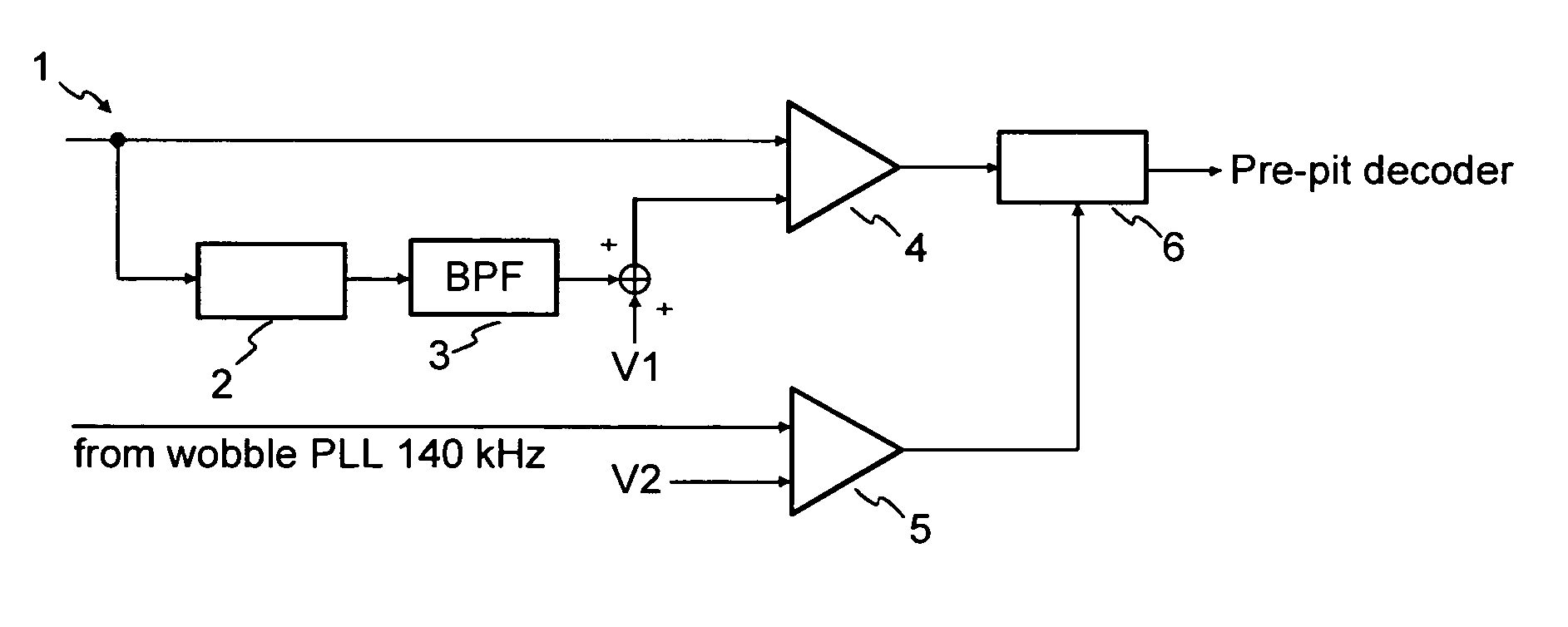
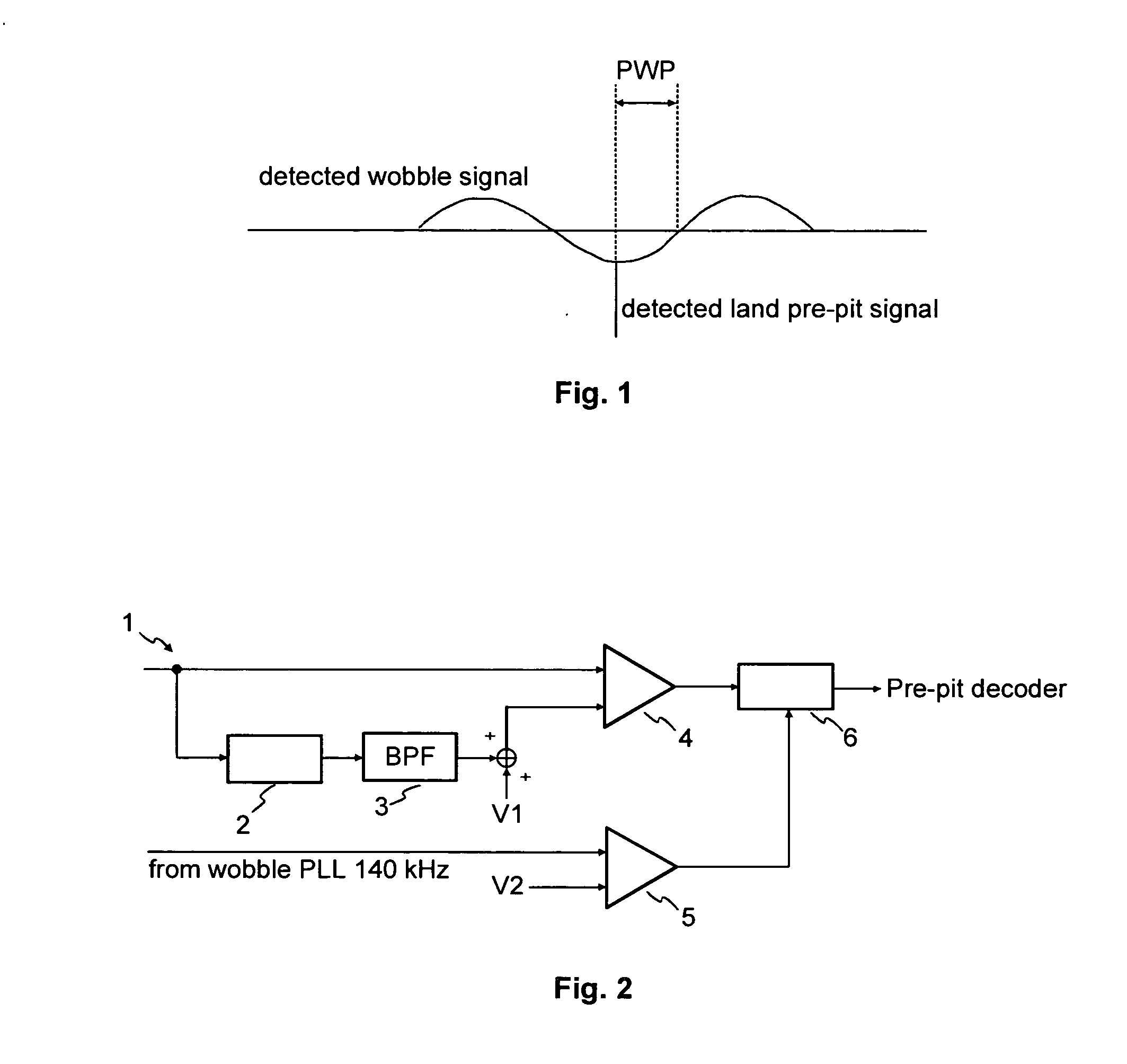
[0012] It is an object of the present invention to provide an alternative method and device for securely detecting a land pre-pit signal.
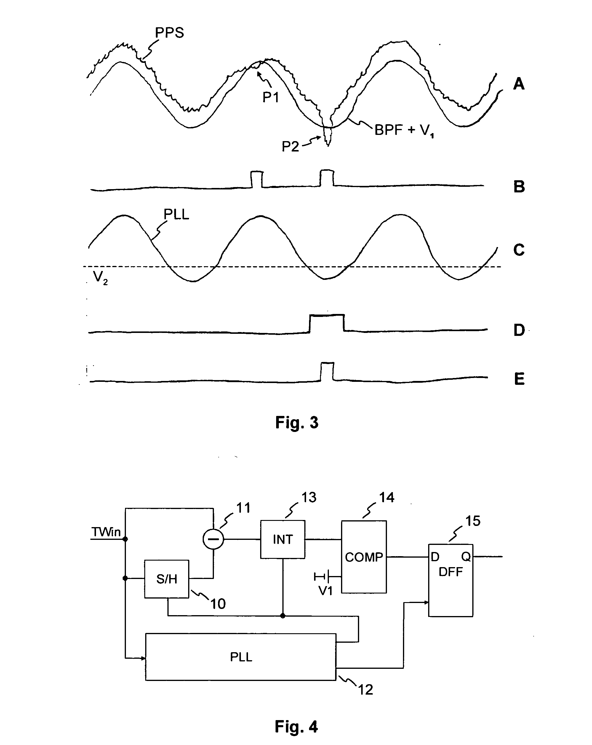
[0015] Compared to known solutions the present invention has the advantage that no band pass filter has to be used, which needs to be tuned according to variations of the rotation speed (CAV mode etc.). Furthermore, the land pre-pit signal obtained according to the present invention shows less dependency on the variations of the input amplitude as no limiter is used. Also the creation of the gate timing shows less dependency on the signal level, as the timing is derived from a clocking instead. Additionally, the land pre-pit signal shows less dependency on the detection window accuracy (phase) as compared to the single shot detection.
[0021] Favourably, the method according to the invention is performed in an apparatus for reading from and / or writing to optical recording media. This allows a reliable detection of the land pre-pits on the optical recording medium.

Problems solved by technology

A further drawback of the standard detector circuit is that the PLL (not shown) must create a synthesized sine wave of constant amplitude to enable the creation of a reliable noise gate signal.

Method used


Image

  • Method and device for detecting land pre-pits
  • Method and device for detecting land pre-pits
  • Method and device for detecting land pre-pits

Examples


first embodiment

[0075] A first embodiment is illustrated in FIG. 21. Since the LPP signal occurs at particular positions of the track wobble signal (FIG. 21A) and has a particular tolerance with respect to this theoretical position, it is possible to control a sample / hold block by a window signal (S / H gate, FIG. 21D) so that a phase error signal distortion received by the signal of FIG. 21B is muted. For this purpose, the sample / hold block is controlled so as to maintain the voltage value of the TW signal during the expected occurrence of the LPP signal. Right after the expected end of the LPP the sample / hold block is deactivated again.

[0076] A first embodiment of a PLL 12 according to the invention is illustrated in FIG. 24. A sample / hold block 126 is connected in front of the phase detector 120. The sample / hold block can save the value of an input signal at the beginning of a time interval determined by a control signal (S / H gate, not shown) and can freeze this value until the end of the time int...

second embodiment

[0079] A second embodiment for generating a phase error signal not being affected by LPP is shown in FIG. 26. Within the time interval in which the LPP occurs, the phase error signal is switched to zero. For this purpose, a switch 127 is inserted between phase detector output and loop filter 121. The resulting phase error signal is shown in FIG. 22E (analogous in FIG. 22C). Due to the muting, see FIG. 22D, of the faulty phase error signal during occurrence of the LPP the average value of the corrected phase error signal (FIG. 22E) remains zero. If necessary, the time interval in which the generation of the phase error signal is muted may be extended to the entire half wave of the track wobble Signal in which a LPP is situated (FIG. 23).

[0080] An alternative to the embodiment shown in FIG. 26 is, instead of the square-wave signal controlling the multiplication (+1; −1), to generate a signal which defines three factors (+1; 0; −1) for multiplication. The positions at which one of the ...


PUM


Abstract

The address information of DVD-R or DVD-RW discs should be identified more accurately. Therefore, the detector is implemented with a sample / hold device for storing a reference value to be used for a sampling window. An optional integrator is used for comparing the integrated signal with a reference value to decide on the presence of a land pre-pit. The timing for controlling both the sample / hold device and the integrator is derived from a phase locked loop that is locked to the incoming groove wobble signal (TWin) by performing a clock multiplication with a predetermined factor. Advantageously, no band pass filter has to be included, which would need to be tuned according to the variations of the disc speed. Furthermore, the proposed land pre-pit detector is less affected by variations of the input amplitude, as no limiter is used.

Description

FIELD OF THE INVENTION [0001] The present invention relates to a method for detecting marks on an optical recording medium including the step of scanning a track on the optical recording medium by obtaining a scanning signal including information about the marks to be detected. Furthermore, the present invention relates to a corresponding device for detecting marks on the optical recording medium BACKGROUND OF THE INVENTION [0002] In the known ECMA-279 standard for DVD-R (“ECMA—Standardizing Information and Communication Systems: 80 mm (1.23 Gbytes per side) and 120 mm (3.95 Gbytes per side) DVD-Recordable Disk (DVD-R)”) and the ECMA 338 standard for DVD-RW (“ECMA—Standardizing Information and Communication Systems: 80 mm (1.46 Gbytes per side) and 120 mm (4.70 Gbytes per side) DVD Re-recordable Disk (DVD-RW)”) the address information to identify a position on an unrecorded disc is stored in the so-called land pre-pits (LPP). These pre-pits are situated in the lands, which are the a...

Claims


Application Information

Patent Timeline
IPC IPC(8): G11B7/005G11B20/10G11B7/007G11B7/09G11B20/14G11B27/19G11B27/24G11B27/30
CPCG11B7/0053G11B7/24082G11B20/1403G11B2220/2562G11B27/3027G11B2220/216G11B2220/218G11B27/24G11B7/09
Inventor BUCHLER, CHRISTIAN
Owner THOMSON LICENSING SA
Learn More