Image encoding apparatus and method

a technology of image encoding and encoding apparatus, applied in the field of image encoding apparatus and method, can solve the problems of image quality degradation, large calculation load, and control of bit rate for a minimum numerical distortion

Inactive Publication Date: 2005-01-06
SONY CORP
View PDF2 Cites 54 Cited by
  • Summary
  • Abstract
  • Description
  • Claims
  • Application Information

AI Technical Summary

Benefits of technology

[0011] It is therefore an object of the present invention to overcome the above-mentioned drawbacks of the related art by providing an image encoding apparatus and method, capable of controlling the quality of an image resulted from compression of an image having a predetermined resolution (corresponding to the aforementioned image whose resolution is 1000×500) and that is a part of an original image (corresponding to the image whose resolution is 2000×1000) and maintaining the quality of the image resulted from compression of the original image at a high level.
[0013] In the above image encoding apparatus and method, the quantization-step size set, during the quantization, for the subband whose resolution level belongs to the predetermined resolution is made to coincide with the quantization-step size set for each subband to quantize the predetermined resolution level as that of an original image. Thus, by controlling the quality of a compressed image of a subband whose resolution level belongs to the predetermined resolution level to approximate that of a compressed image resulted from compression of an image having initially the resolution level, it is possible to maintain the quality of a compressed image resulted from compression of an original image at a high level.

Problems solved by technology

However, if the bit rate for encoding is smaller than necessary, the block distortion peculiar to the DCT will be remarkable and a resultant image will appear noticeably degraded in quality.
Such rate control is versatile but disadvantageous in that the load of calculation is very great.
Also, the technique of controlling a bit rate for a minimum numerical distortion is disadvantageous in that it cannot assure a highest quality of an image when viewed by the human being.

Method used


Image

  • Image encoding apparatus and method
  • Image encoding apparatus and method
  • Image encoding apparatus and method

Examples


Embodiment Construction

[0030] The present invention will be described in detail below concerning an embodiment thereof with reference to the accompanying drawings.

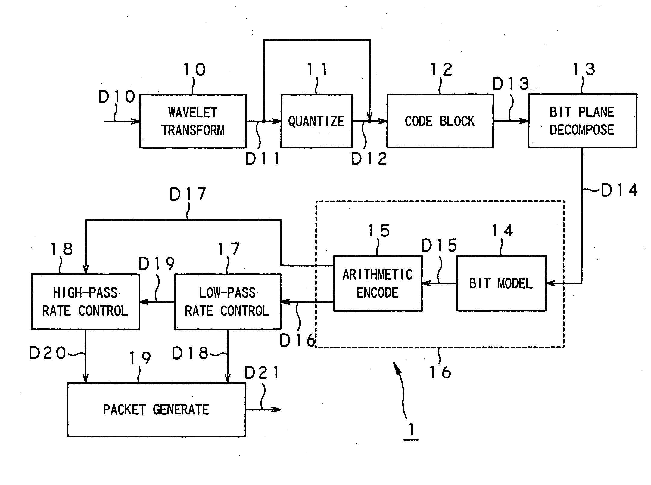
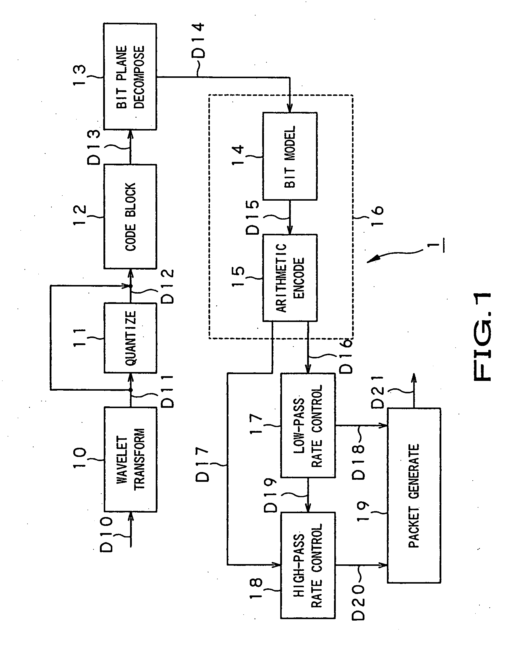
[0031] Referring now to FIG. 1, there is schematically illustrated in the form of a block diagram an image encoder according to an embodiment of the present invention. As shown in FIG. 1, the image encoder, generally indicated with a reference 1, includes a wavelet transformer 10, quantizer 11, code blocking unit 12, bit plane decomposer 13, bit modeling unit 14, arithmetic encoder 15, low-pass rate controller 17, high-pass rate controller 18, and a packet generator 19. The bit modeling unit 14 and arithmetic encoder 15 form together an EBCOT (embedded coding with optimized truncation) unit 16.

[0032] The wavelet transformer 10 is normally a filter bank including a low-pass filter and a high-pass filter. It should be noted that a digital filter has to be pre-buffered with a sufficient amount of input images for filtering since it normally shows...


PUM


Abstract

In an image encoder (1), a quantizer (11) makes a quantization-step size set for each of low-frequency subbands whose resolution level belongs to a predetermined resolution level coincide with a quantization-step size set for each subband to encode an original image having the resolution level as it is. A low-pass rate controller (17) provides a rate control for the bit rate of arithmetic code D16 in all code blocks in a low-frequency subband to be less than a predetermined target bit rate. A high-pass rate controller (18) provides such a rate control that the bit rate of arithmetic code D17 in all code blocks in other subbands than the low-frequency subbands will be less than a target bit rate, that is, a bit rate resulted from subtraction of a bit rate D18 having actually occurred in the low-frequency subbands from a final target bit rate.

Description

BACKGROUND OF THE INVENTION [0001] 1. Field of the Invention [0002] The present invention generally relates to an image encoding apparatus and method, for compressing an input image according to the JPEG-2000 Standard, for example. [0003] This application claims the priority of the Japanese Patent Application No. 2003-127409 filed on May 2, 2003, the entirety of which is incorporated by reference herein. [0004] 2. Description of the Related Art [0005] One of the typical techniques of image compression is defined in the JPEG (Joint Photographic Experts Group) standardized by the ISO (International Standards Organization). The JPEG uses the DCT (discrete cosine transform) to provide quality encoded images and decoded images in case a relatively high bit rate is assigned for the encoding. However, if the bit rate for encoding is smaller than necessary, the block distortion peculiar to the DCT will be remarkable and a resultant image will appear noticeably degraded in quality. [0006] On...

Claims


Application Information

Patent Timeline
Patent Type & Authority Applications(United States)
IPC IPC(8): G06K9/36H03M7/30H04N1/41H04N19/115H04N19/126H04N19/134H04N19/146H04N19/147H04N19/169H04N19/186H04N19/196H04N19/34H04N19/60H04N19/635H04N19/85H04N19/91
CPCH04N19/13H04N19/647H04N19/63H04N19/146H04N19/61H04N19/124H04N19/115
Inventor FUKUHARA, TAKAHIROKIMURA, SEIJI
Owner SONY CORP
Why Eureka
Try Eureka