Method for embedding a marking substance in a device such as an insertion tube

a permanent marking and insertion tube technology, applied in the field of permanent marking devices, can solve the problems of bleaching of photosensitive materials, and achieve the effect of high contrast, resistance to abrasion and chemical degradation

Inactive Publication Date: 2005-01-06
OPTIM
View PDF19 Cites 35 Cited by
  • Summary
  • Abstract
  • Description
  • Claims
  • Application Information

AI Technical Summary

Benefits of technology

[0006] In one aspect of the invention, a marking material is applied to the surface of the insertion tube, and an ultrasonic device or laser is used to embed the marking material into the insertion tube material, commingling the two materials below the exterior surface of the tube. The result is a marking that is not simply a coating on the surface of the tube, but rather is an integral part of the tube material. This creates a more durable mark that is more resistant to abrasion and chemical degradation. Also, the marking material can be chosen such that it provides a high contrast to the color of the insertion tube or catheter material. The marking material may be any material that can be embedded into the surface of the tube. This can include such material as, but not limited to, lubricating coatings such as parylene, molybdenum disulphide, PTFE, and the like; or, pigments such as titanium dioxide (commonly used to color white paints); colored epoxy; or a material similar to the substrate but with a different, contrasting color. Insertion tubes are typically made of polyurethane, and an appropriate marking material can be a different color polyurethane or another organic polymer that can be embedded into polyurethane.

Problems solved by technology

Laser marking may also involve material removal through ablation or evaporation, and can produce bleaching of photosensitive materials.

Method used


Image

  • Method for embedding a marking substance in a device such as an insertion tube
  • Method for embedding a marking substance in a device such as an insertion tube

Examples


Embodiment Construction

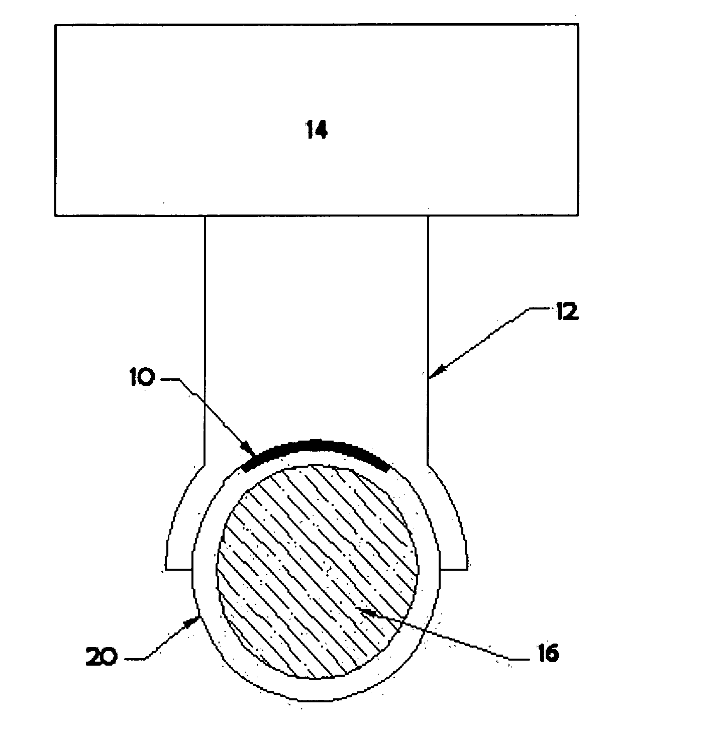
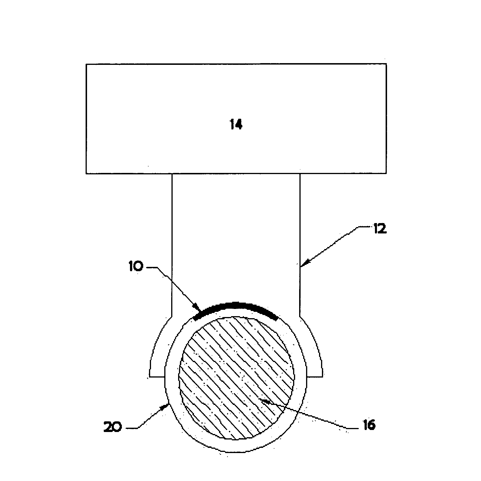
[0010] The preferred embodiment of the present invention is accomplished in a process in which a marking substance (such as titanium dioxide or other pigment materials, urethane, PTFE, paint, epoxy, and the like) is ultrasonically embedded into an insertion tube, preferably but not exclusively the (typically polyurethane) insertion tube of a medical device. See the attached figure. Markings 10 to be embedded in tube 20 are painted or silk screened onto the exterior of tube 20, and either allowed to cure, or alternatively, cured after the ultrasonic embedding process. An ultrasonic “horn”12 of suitable shape to make intimate contact with at least the area of the tube that carries the marking is then placed over marking 10, while a suitably-shaped “anvil”16 is placed within tube 20. Pressure is applied to the tube and marking by means of the anvil and horn being pressed together, with the marking therebetween. The vibration and heat produced by the ultrasonic wave produced by transduc...


PUM

PropertyMeasurementUnit
energyaaaaaaaaaa
insertion depthaaaaaaaaaa
coloraaaaaaaaaa

Abstract

A method of embedding a marking substance in an object to be marked, to create one or more visible markings on the object. A marking material is used to create one or more visible markings on the object. The marking material is placed on the surface of the object. A source of energy that is sufficient to cause the marking material to become embedded in the object is applied, to create one or more visible markings on the object.

Description

CROSS REFERENCE TO RELATED APPLICATION [0001] This application claims priority of Provisional application Ser. No. 60 / 466,264, filed on Apr. 29, 2003.FIELD OF THE INVENTION [0002] This invention relates to a process for permanently marking devices such as endoscope insertion tubes. BACKGROUND OF THE INVENTION [0003] In the fields of medical endoscopy, catheterization and ultrasound, it is often desirable or necessary to mark the exterior surface of the insertion tube, either an endoscope (visual, video, ultrasound, spectroscopic) or catheter, with length markers or other markings. This is done so the operator knows the depth the device has been inserted into the patient and the orientation of the device. There are a limited number of materials these tubes are manufactured from because of the biocompatibility or mechanical properties of these devices. It is often difficult to produce markings on these materials for a variety of reasons. One reason is that paints, epoxies, or other ma...

Claims


Application Information

Patent Timeline
Patent Type & Authority Applications(United States)
IPC IPC(8): A61B1/00A61B19/00B41M5/26
CPCA61B2019/5437A61B1/0011A61B1/00071B41M5/267A61B2090/3937
Inventor KRUPA, ROBERT J.
Owner OPTIM
Why Eureka
Try Eureka