
Surface acoustic wave device

a surface acoustic wave and waveguide technology, applied in the direction of impedence networks, electrical devices, transmission, etc., can solve the problems of increasing the attenuation amount, decreasing the insertion loss, and the characteristics of the surface acoustic wave device are becoming critical, so as to increase the insertion loss, and improve the insertion loss

Active Publication Date: 2005-01-06
TAIYO YUDEN KK
View PDF5 Cites 0 Cited by
  • Summary
  • Abstract
  • Description
  • Claims
  • Application Information

AI Technical Summary

Benefits of technology

[0009] With the foregoing in view, the present inventor continued research and development on the configuration of the surface acoustic wave device which implements a narrower band without increasing insertion loss, and discovered that attenuation outside the pass band can be increased without increasing insertion loss, and fine filter characteristics in a narrow band can be implemented by forming the reflection electrode 2 and the reflection electrode 3 as blocks with different reflection coefficients.
[0010] Therefore based on this discovery, an object of the present invention is to provide a surface acoustic wave device which can decrease insertion loss in the pass band and present good narrow band characteristics.

Problems solved by technology

When the surface acoustic wave device is used as a filter, a critical issue is decreasing the insertion loss and increasing the attenuation amount outside the pass band in order to allow necessary signals to pass and to remove unnecessary signals.
Also as the number of components decreases for downsizing the radio device main body, characteristics demanded for the surface acoustic wave device are becoming critical.
This however increases insertion loss.
Another method of implementing a narrower band is decreasing stop band width by decreasing the reflection coefficient of the reflection electrodes 2 and 3, but this also has a tendency to increase insertion loss accordingly.

Method used


Image

  • Surface acoustic wave device
  • Surface acoustic wave device
  • Surface acoustic wave device

Examples


Embodiment Construction

[0028] Embodiments of the present invention will now be described with reference to the accompanying drawings. The embodiments shown in the drawings are for describing the present invention, and application of the present invention is not limited to these.

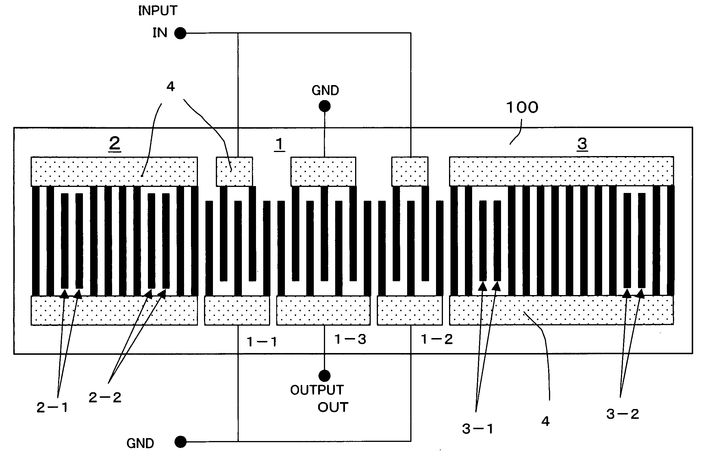
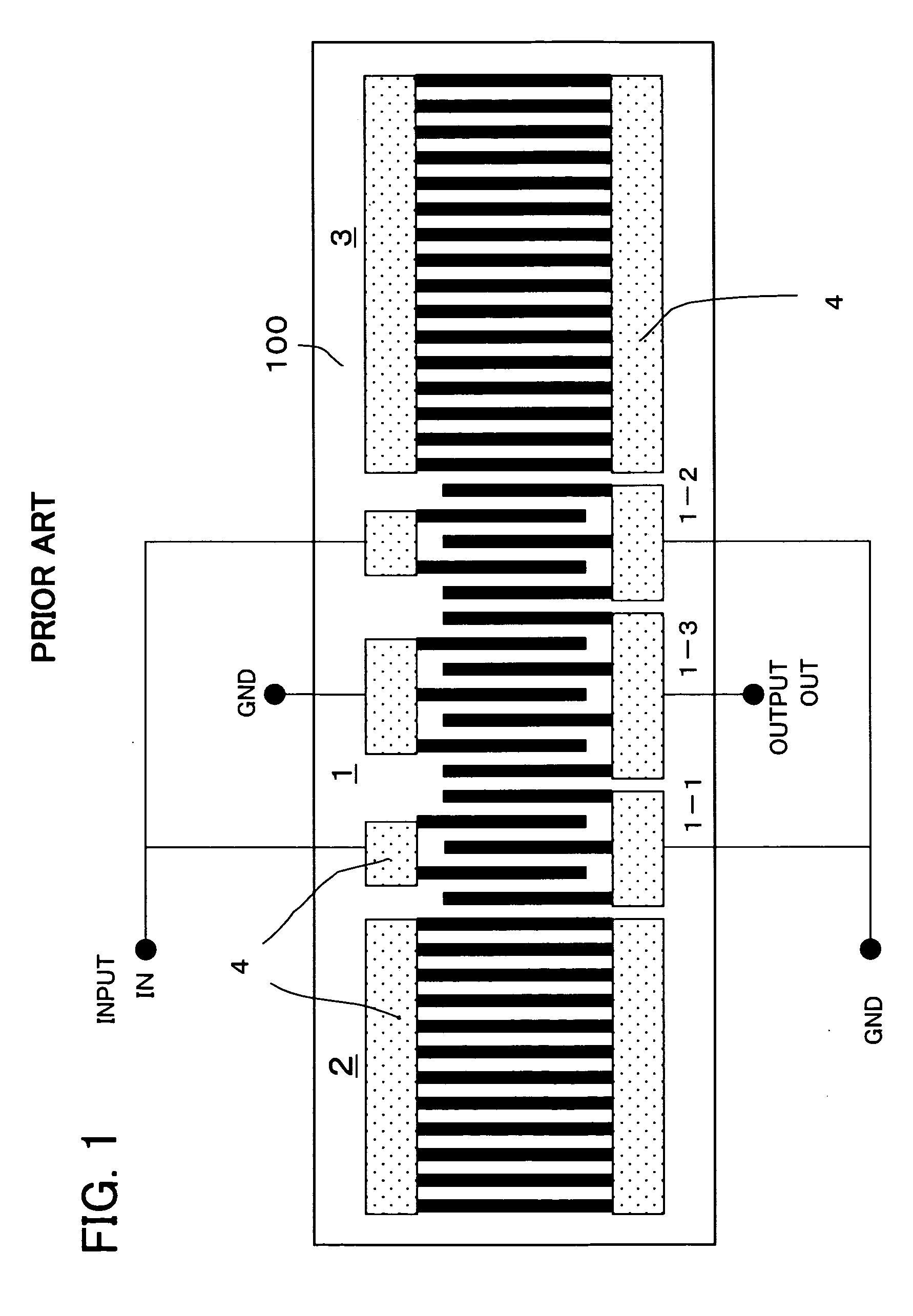
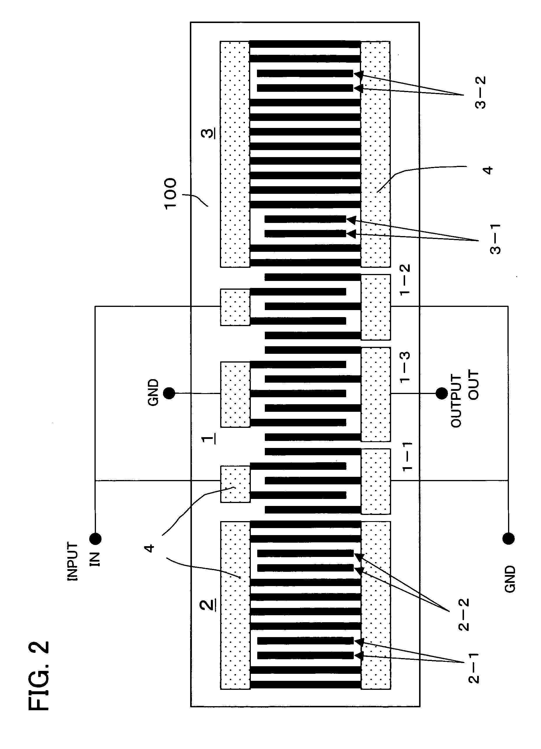
[0029]FIG. 2 is an embodiment of the present invention, and just like the configuration shown in FIG. 1, electrode fingers, of which the main component is Al, are formed on the LiTa03 or LiNb03 piezoelectric substrate 100, and the interdigital transducer (IDT) 1, which has three drive electrodes 1-1, 1-2 and 1-3, is cascade-connected between the two reflectors 2 and 3.

[0030] As a feature of the present invention, the difference from the configuration in FIG. 1 is that the reflectors 2 and 3 are comprised of a plurality of blocks having different reflection coefficients. In other words, each one of the reflectors 2 and 3 has three blocks with different reflection coefficients, and the blocks with different reflection coefficients ...


PUM


Abstract

A surface acoustic wave device for implementing an attenuation characteristic outside of the pass band and the narrow band characteristics, preferably for use as a filter. The surface acoustic wave device includes a piezoelectric substrate, interdigital transducers formed on the piezoelectric substrate, and first and second reflectors disposed on the sides of the interdigital transducers. Each of the first and second reflectors includes an open electrode block with a plurality of electrically independent electrode fingers, and a short electrode block with a plurality of electrode fingers of which both ends are electrically shorted.

Description

TECHNICAL FIELD [0001] The present invention relates to a surface acoustic wave device, and more particularly to a surface acoustic wave device which can implement the attenuation characteristic outside the pass band and the narrow band characteristics, and is preferable for use as a filter. BACKGROUND ART [0002] Recently radio devices, including portable telephones, cordless telephones and radio sets, are constantly becoming smaller and lighter, and their use is spreading rapidly. For the high frequency circuits of these radio devices, filter elements are used as critical key devices. [0003] Therefore corresponding to the demands of smaller size and light weight for radio devices, smaller and lighter filter elements are demanded. As a configuration to make a filter element smaller and lighter, a surface acoustic wave device is used. [0004] When the surface acoustic wave device is used as a filter, a critical issue is decreasing the insertion loss and increasing the attenuation amou...

Claims


Application Information

Patent Timeline
Patent Type & Authority Applications(United States)
IPC IPC(8): H03H9/145H03H9/02
CPCH03H9/02771H03H9/145
Inventor KAWACHI, OSAMUABE, TAKUYAKANEDA, YASUFUMITAJIMA, MOTOYUKI
Owner TAIYO YUDEN KK
Learn More