

Electrotransport device having a reservoir housing having a flexible conductive element
a technology of flexible conductive elements and electrotransport devices, which is applied in the direction of sugar derivates, esterified saccharide compounds, and therapy, etc., can solve the problems of limiting the patient's movement and mobility, affecting the patient's comfort,
- Summary
- Abstract
- Description
- Claims
- Application Information
AI Technical Summary
Benefits of technology
Problems solved by technology
Method used
Image

Examples
Embodiment Construction
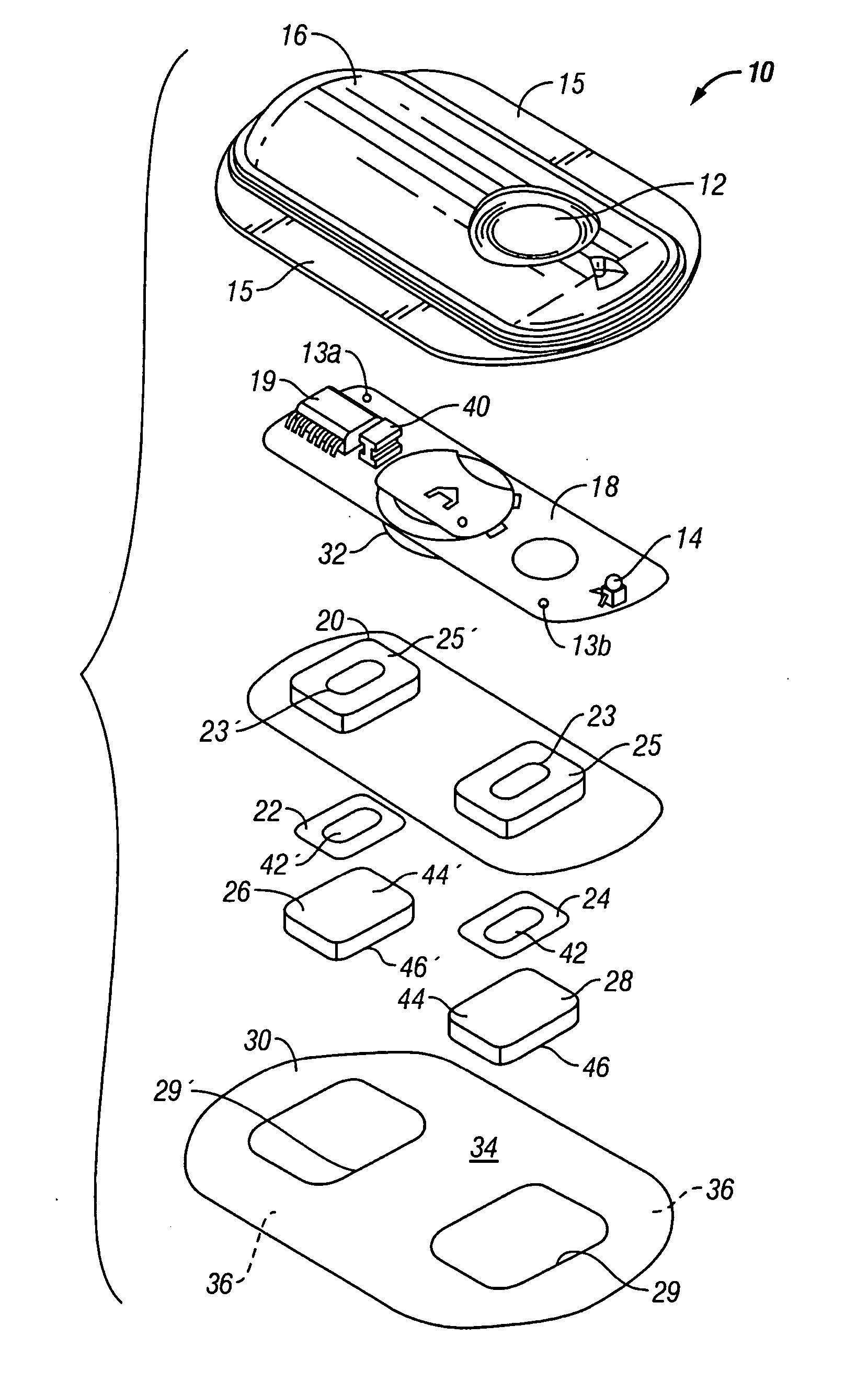
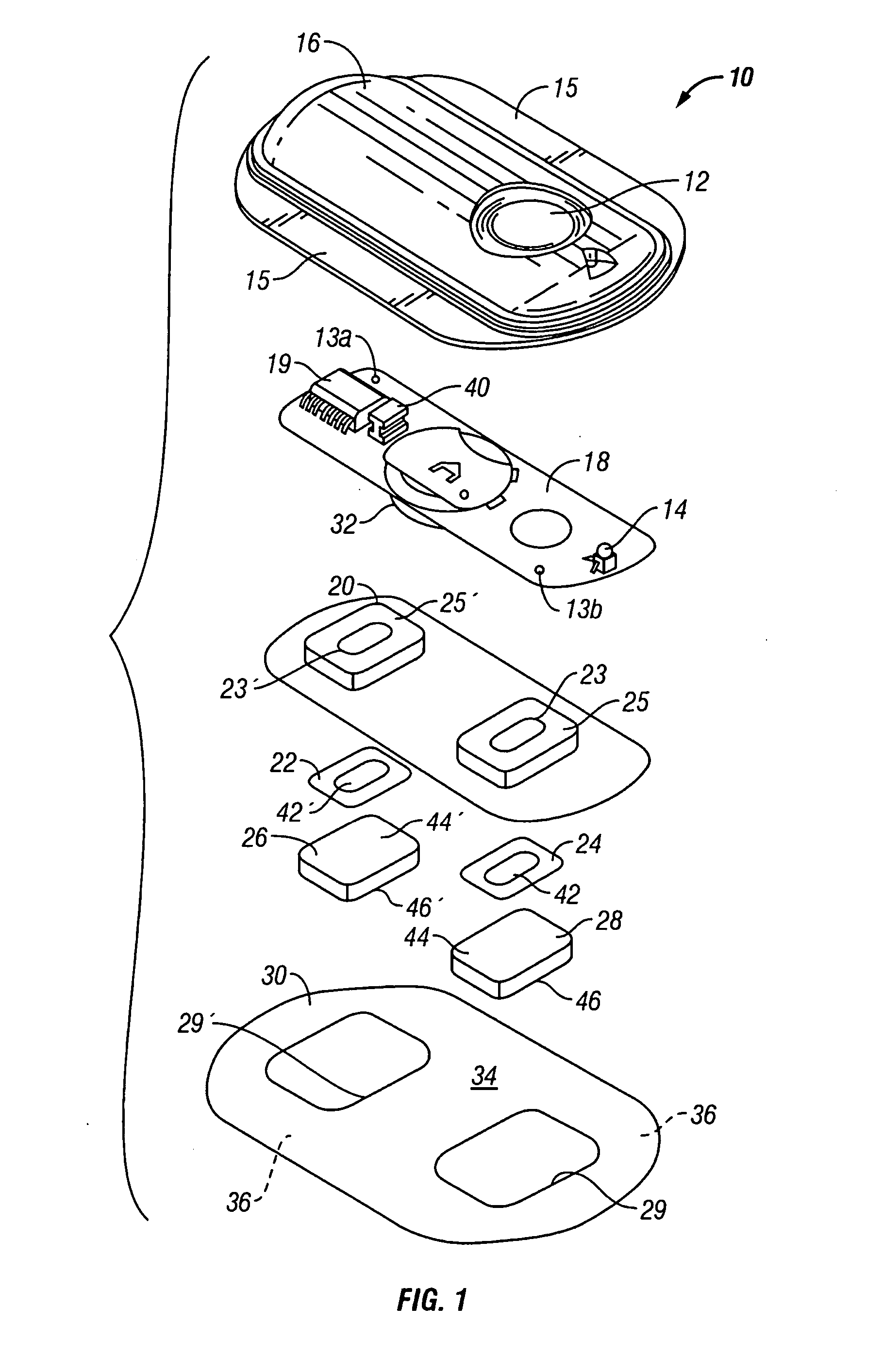
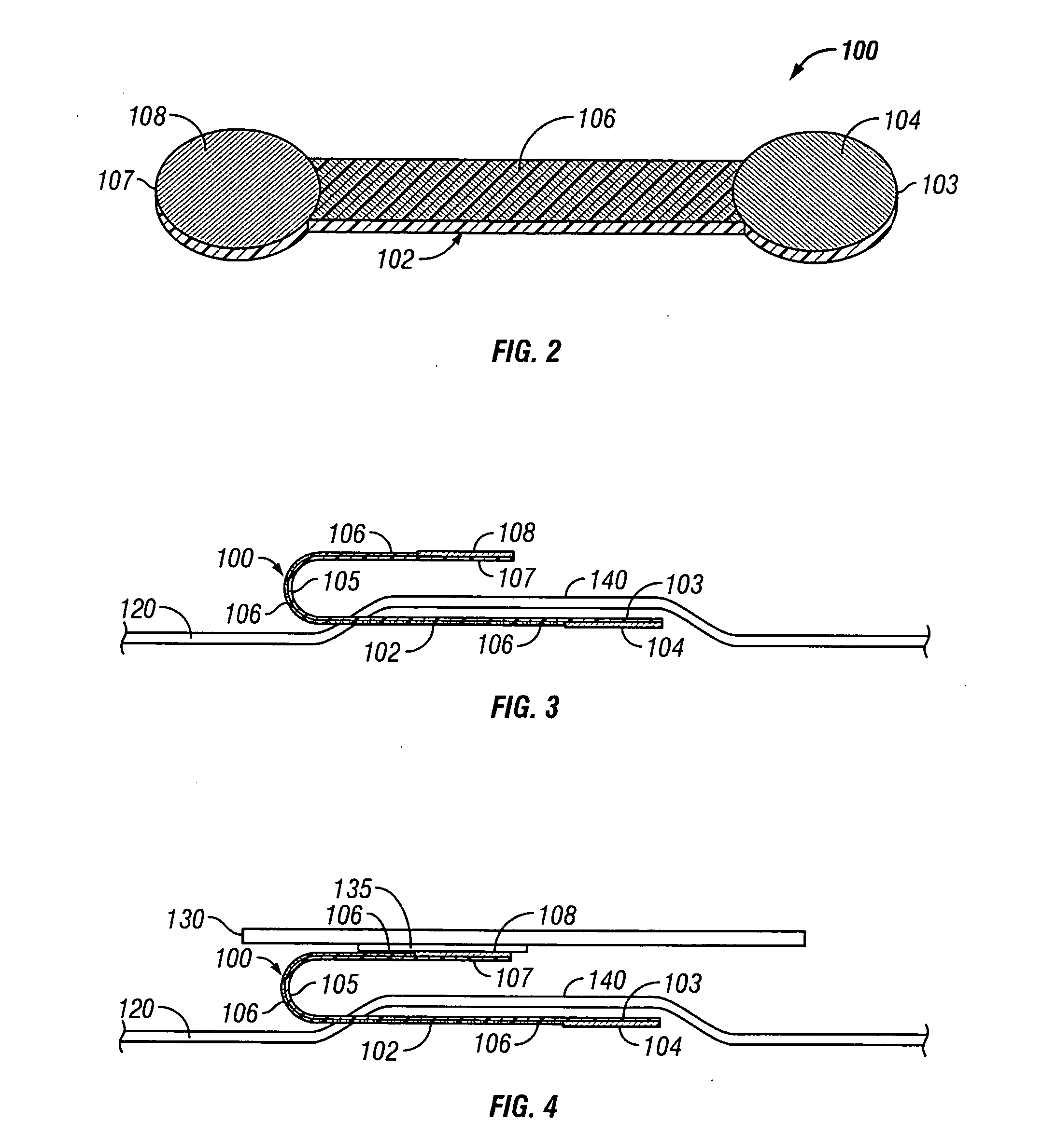
[0025] The present invention provides an electrotransport reservoir housing having a flexible conductive element integrally molded within the insulated housing so that a first portion of the element is within the housing and the second portion is outside of the housing. The incorporation of this flexible conductive element as part of the reservoir housing enables placing the drug reservoir and electrode, which are inside of the reservoir housing, in electrical communication with a power source outside of the reservoir, without the need for an opening to be formed in the reservoir housing after it has been formed. Because the molding process is performed at high heat and pressure, there is a very tight, liquid and moisture impermeable bond that is created between the material forming the reservoir housing and the conductive element. This results in a reservoir housing that is essentially a single integral component that does not require the fabrication of openings or other passages t...
PUM
| Property | Measurement | Unit |
|---|---|---|
| temperatures | aaaaa | aaaaa |
| conductive | aaaaa | aaaaa |
| flexible | aaaaa | aaaaa |
Abstract
Description
Claims
Application Information