
Method and device for interleaving and method and device for de-interleaving

a technology of interleaving and interleaving devices, applied in the direction of channel coding adaptation, instrumentation, signal error generation in digital data, etc., can solve the problems of low average code error rate, easy burst error generation, and low interleaving error ra

Inactive Publication Date: 2005-01-06
KOKUSA ELECTRIC CO LTD
View PDF19 Cites 6 Cited by
  • Summary
  • Abstract
  • Description
  • Claims
  • Application Information

AI Technical Summary

Benefits of technology

The present invention was devised in light of the above-described state of affairs, and has as its object to provide an interleaving method, interleaving device, de-interleaving method, and de-interleaving device which make it possible to transmit bits that form data in a suitable configuration for said data by executing separate randomization for each datum forming a frame.

Problems solved by technology

In digital telecommunications systems that transmit digital data, signal errors can be generated in digital data in the process of transmission, so encoding is carried out through the use of error-correcting codes for the digital data to be sent.
Although the average code error rate itself is low in telecommunications environments such as mobile telecommunications, burst errors readily occur.
Consequently, even if data is transmitted with error correction encoding, burst errors often occur with the number of consecutive bits exceeding the error correcting capacity.
For this reason, the use of error-correcting codes in mobile telecommunications environments is less effective than in telecommunications environments where random code errors are generated.
First, suppose that a burst error with a bit length of m×k occurs in an interleaved frame during the transmission process.
That is to say, said code error becomes a random code error for the frame after de-interleaving.
However, since it is necessary to store at least one frame's worth of bits in order to deploy interleaving on the transmission side and de-interleaving on the receiving side, respectively, a delay unavoidably occurs.
When said interleaving is executed with respect to the entire bit sequence forming such a single frame, the following problems occur since randomization of burst errors is also carried out on portions that have not undergone error correction encoding.
Thus, randomization due to interleaving is not desirable in relation to portions that have not undergone error correction encoding.
In such cases, a sufficient randomization effect can be realized with regard to a specified error correction code when interleaving is deployed across an entire frame using as a standard the code length of said specified error correction code within the frame, but there arises the problem that a sufficient randomization effect is not realized with regard to other error correction codes with different code lengths.
For each datum forming a frame, it would be advantageous to determine whether or not randomization is appropriate by seeking an approach that suits the nature of the data in question, but until now, no technological means have been provided for this purpose.

Method used


Image

  • Method and device for interleaving and method and device for de-interleaving
  • Method and device for interleaving and method and device for de-interleaving
  • Method and device for interleaving and method and device for de-interleaving

Examples


first embodiment

A. First Embodiment

(1) The Interleaving Device

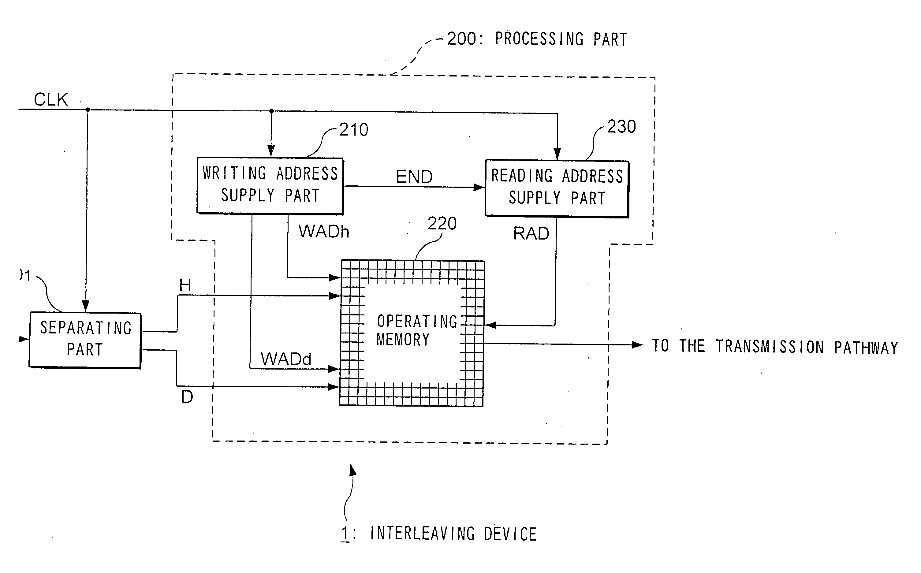
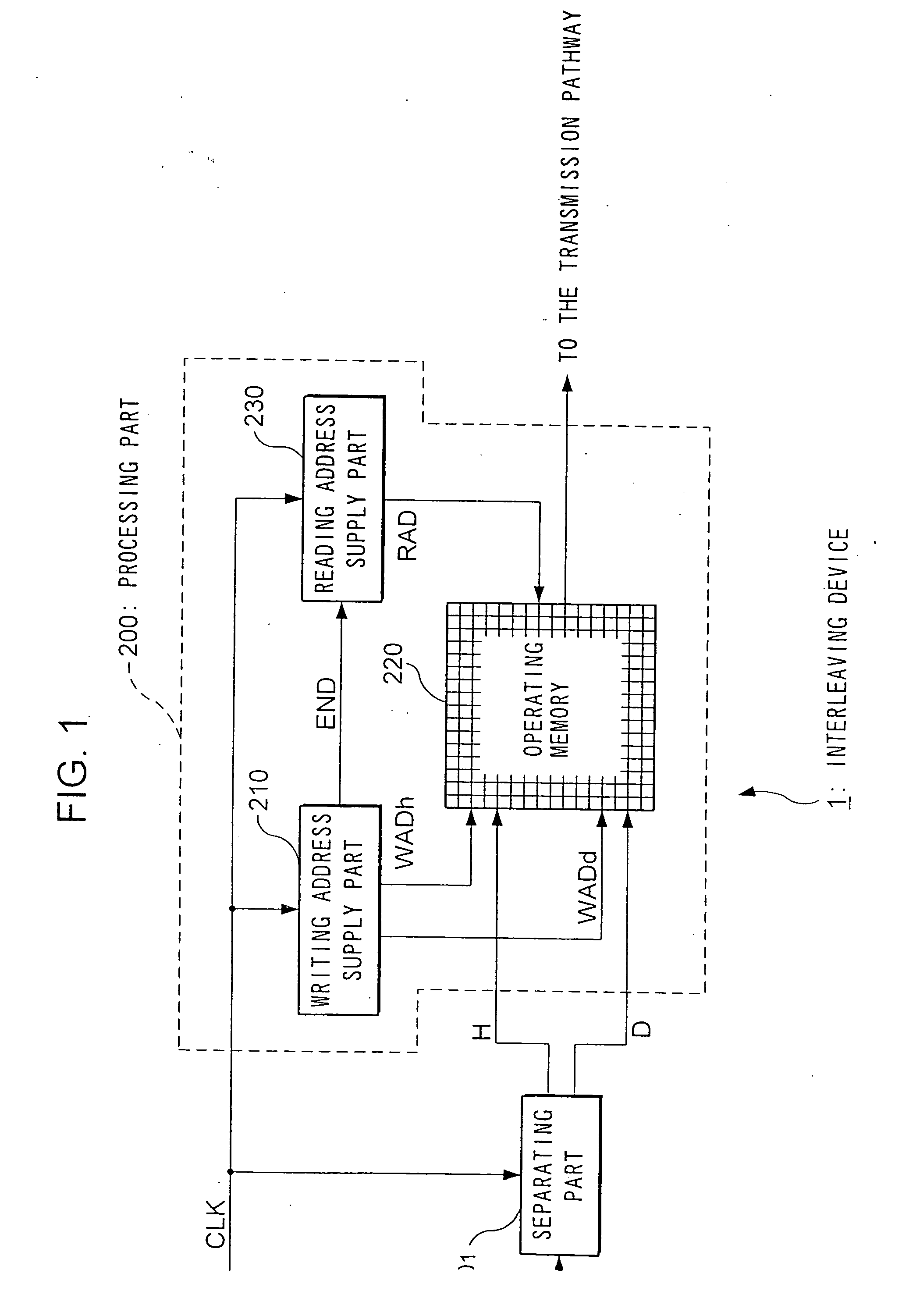
FIG. 1 is a block diagram showing a configuration of an interleaving device 1 provided to a device on the transmission side of a digital telecommunications system which is the first embodiment of this invention.

As shown in FIG. 1, this interleaving device comprises a separating part 100, and a processing part 200.

The frames that are to be transmitted to the receiving side device are sequentially transmitted to the interleaving device 1. Each frame is a bit sequence formed from a plurality of bits, and these bits are sequentially supplied to the interleaving device 1 synchronously with a bit clock CLK.

When the data forming the frames are divided by category, it is possible to distinguish between the header H and the data D which follows it.

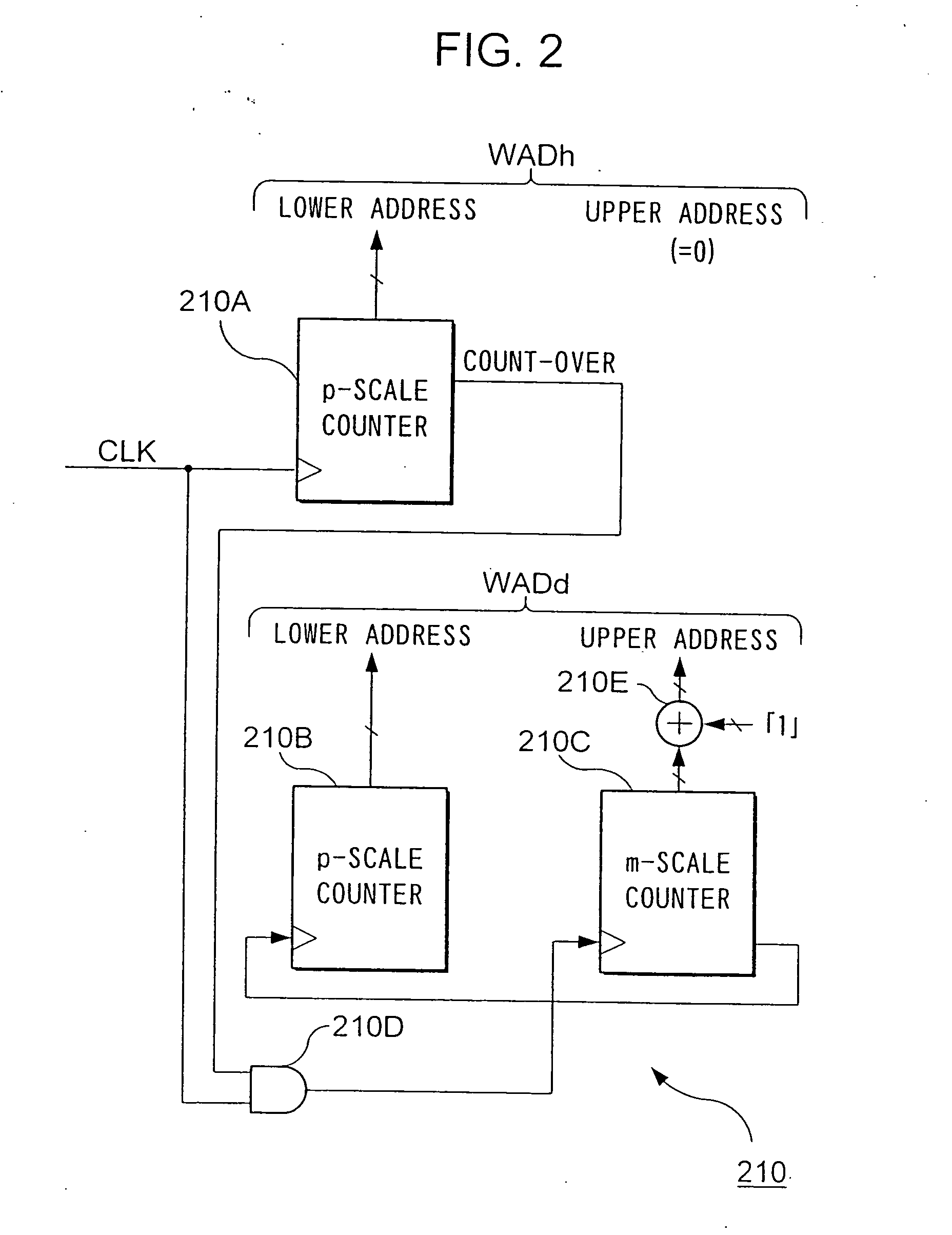
In the example described below, the header H is formed from p bits, and the data D is formed from m×p bits.

Furthermore, the header H undergoes error correction encoding. By contrast, the dat...

third embodiment

C. Third Embodiment

In the first and second embodiments, the frame to be transmitted is separated into the part that has undergone error correction encoding and the part that has not undergone error correction encoding, and interleaving is performed by scattering and arranging the bits making up the former across the entire range of the bit sequence of the latter.

Embodiments of interleaving in the present invention are not limited to the above.

For example, there is the case where data that has not undergone error correction encoding contain types of data strings that, because of their nature, should undergo the randomization effect of interleaving.

The present embodiment assumes this type of case. In the present embodiment, the data that has not undergone error correction encoding is divided into a part for which the randomization effect of interleaving is desirable, and a part for which it is not desirable, and interleaving is performed by scattering and arranging the bits tha...


PUM


Abstract

The writing address supply part 210 supplies writing addresses for writing the bits forming bit sequences corresponding to the header H contained in a frame to be transmitted or stored and bit sequences corresponding to the data D, into the operating memory 220. The reading address supply part 230 alternately supplies to the operating memory 220 a plurality of addresses for reading a plurality of continuous bits corresponding to the header H from the operating memory 220, and an address for reading 1 bit corresponding to the data D from the operating memory 220, and reads the bit sequence such that the bits forming the bit sequence corresponding to the header H are scattered and arranged within the bit sequence forming the data D, from the operating memory. In accordance with such an interleaving device, it is possible to individually randomize frames according to their constituent data, and it is possible to transmit the bits that make up such data in a format which is most suited for said data.

Description

TECHNICAL FIELD This invention relates to a method for interleaving and a device for interleaving used in transmitters for digital telecommunications systems and digital recording devices for recording digital data in recording media, and this invention also relates to a method for de-interleaving and a device for de-interleaving used in receivers for digital telecommunications systems and devices for reproducing digital data from recording media. BACKGROUND ART In digital telecommunications systems that transmit digital data, signal errors can be generated in digital data in the process of transmission, so encoding is carried out through the use of error-correcting codes for the digital data to be sent. If the number of erroneous bits in one code word is kept below a specified value when creating these error-correcting codes, then it is possible to correct all of the errors at the time of error-correcting decoding on the receiving side. The number of bits that can be corrected p...

Claims


Application Information

Patent Timeline
IPC IPC(8): H03M13/00H03M13/27H03M13/35H04L1/00H04N19/895
CPCH03M13/00H03M13/27H03M13/2703H03M13/2707H03M13/2764H03M13/2792H04L1/0088H03M13/356H04L1/0009H04L1/0025H04L1/007H04L1/0071H04L1/0072H03M13/35
Inventor KAWAHARA, TOSHIROMIKI, TOSHIOHOTANI, SANAESUZUKI, TAKASHI
Owner KOKUSA ELECTRIC CO LTD
Learn More