Methods for dynamo-electric machine insulation handling

a technology of dynamo-electric machines and handling methods, which is applied in the field of methods for dynamo-electric machines insulation handling, can solve the problems of difficult lubrication and maintenance, impede the lubrication of internal mechanisms, and contamination of insulation materials, so as to increase the rate of insulation handling operations, increase the accuracy and reliability of cutting, forming and inserting operations, and increase the rate of shaft rotation

Inactive Publication Date: 2005-01-13
STRATICO GIANFRANCO +1
View PDF14 Cites 4 Cited by
  • Summary
  • Abstract
  • Description
  • Claims
  • Application Information

AI Technical Summary

Benefits of technology

[0006] The displacement and speed profiles of the operating members (e.g., a cutting member, a forming member, an inserting member, etc.) of the armature insulation machine may be controlled by a central drive mechanism. A centrally driven insulation insertion machine may have fewer moving parts, and thus may obtain higher accuracy and reliability of the cutting, forming, and inserting operations.
[0007] The central drive mechanism may include a rotatable shaft and several subsystems for transferring the shaft rotation into translations of the cutting, forming, and inserting members. The rate of the cutting, forming, and inserting may be related to the rate of rotation of the shaft. Increasing the rate of shaft rotation may increase the rate of insulation handling operations (e.g., cutting, forming, inserting, etc.) and thereby increase productivity. Each subsystem may include a plurality of cams that may rotate with the shaft. The plurality of cams may be coupled with one of the operating members so that the movements of the coupled operating member is controlled by the plurality of rotating cams. The cutting, forming, and inserting members may each be coupled to a respective subsystem.
[0008] The central drive mechanism may be enclosed to create a barrier between the drive mechanism and the insulation handling members (e.g., the cutting member, the forming member, the inserting member, etc.). This barrier may allow insulation to be handled externally (e.g., outside of the enclosure) and may prevent the insulation from being contaminated by lubricant for the drive mechanism. Furthermore, external insulation handling members may be more accessible to an operator than the internal handling members in some machines currently known in the art. Increased operator accessability may simplify procedures such as lubrication, startup, and shutdown.

Problems solved by technology

However, such machines typically have a large number of moving mechanical parts and are generally difficult to lubricate and maintain.
Insulation material can become contaminated by lubricating procedures on some insulating handling machines.
Other machines have enclosed insulation handling mechanisms to minimize contamination of the insulation, but such enclosures generally impede lubrication of internal mechanisms.
In addition, closed configurations are cumbersome for setting up machine insulation operations or troubleshooting mechanical problems.
These difficulties increase the likelihood of breakdown and lead to unsatisfactory levels of accuracy, reliability, and productivity.

Method used


Image

  • Methods for dynamo-electric machine insulation handling
  • Methods for dynamo-electric machine insulation handling
  • Methods for dynamo-electric machine insulation handling

Examples


Embodiment Construction

[0016] The present invention is now described in more detail in conjunction with FIGS. 1-6, which are provided to illustrate embodiments of the invention and not for limiting same.

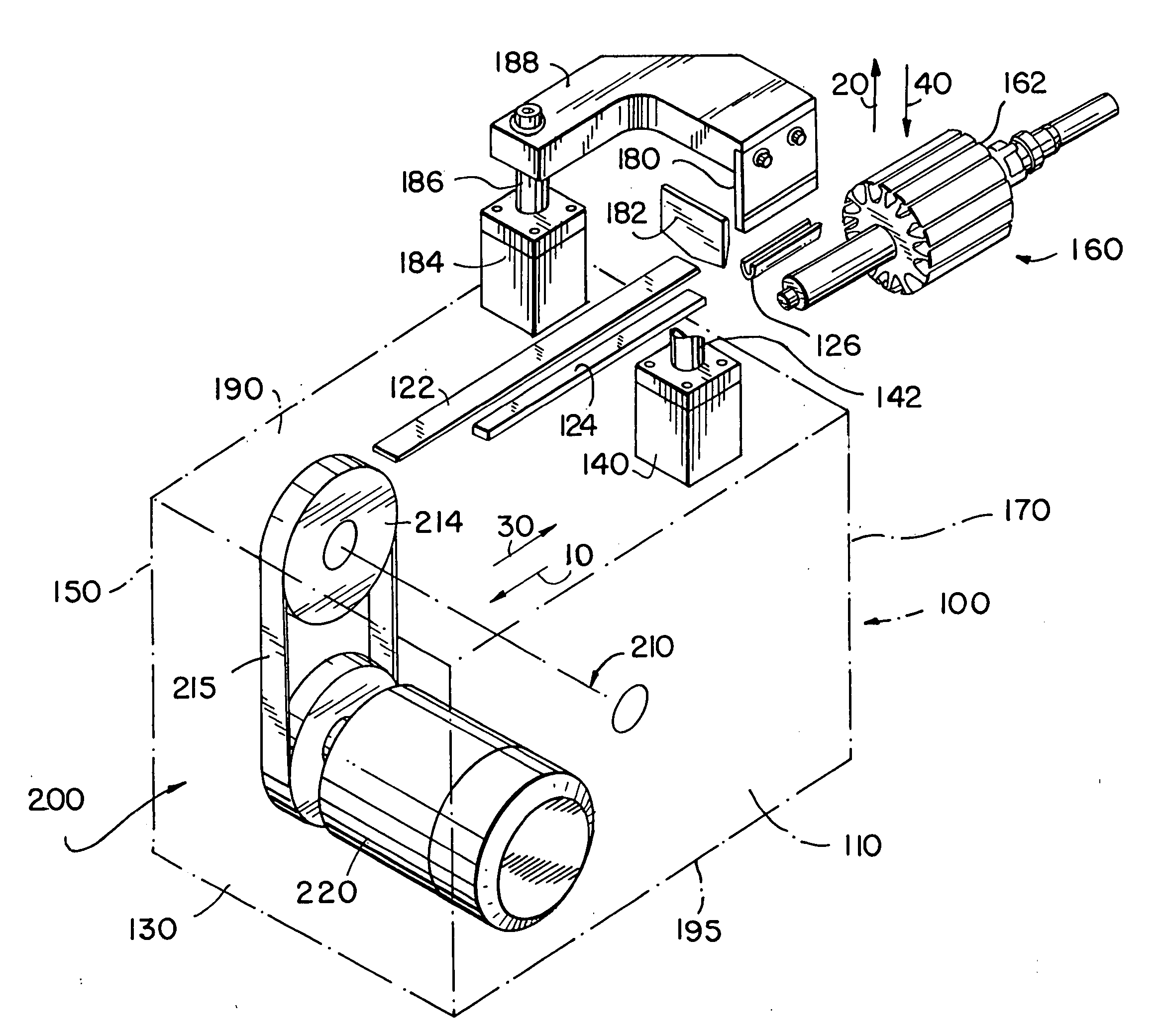
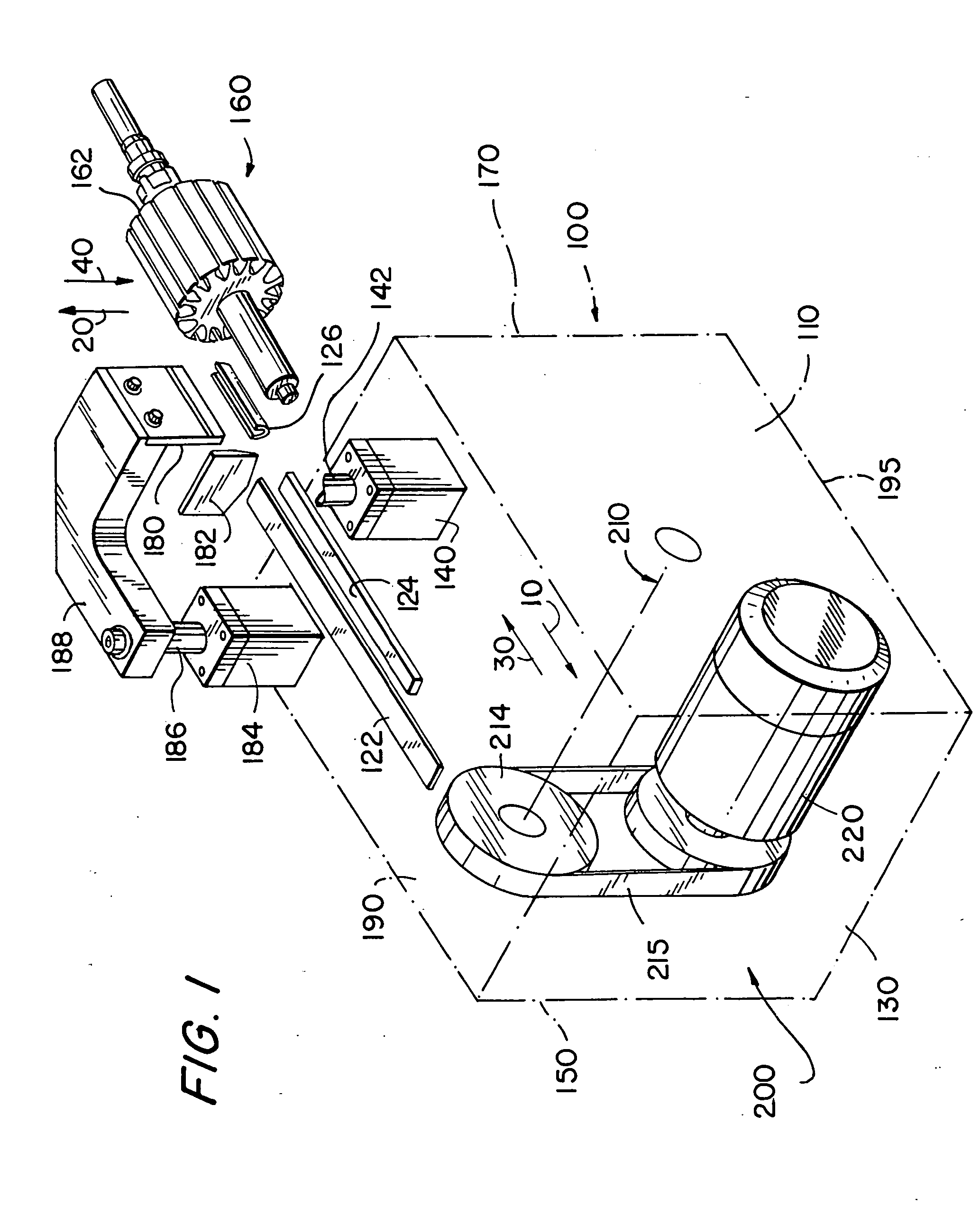
[0017]FIG. 1 depicts, in a perspective partial view, an illustrative insulating apparatus in accordance with various embodiments of the present invention. Certain parts (more fully identified in the following) are omitted for sake of clarity. Drive mechanism 200 may be used to drive the movement, at predetermined timing, of cutting member 182, forming member 180, and inserting member 124. Insert 126, which may be any suitable insulating material, is shown in FIG. 1 already formed and aligned with slot 162 of armature 160, where it may be inserted by inserting member 124.

[0018] During typical use of the apparatus shown in FIG. 1, inserting member 124 may preferably translate in horizontal forward direction 30 to push insert 126 into slot 162 of armature 160. Upon insertion of the insulation material, a su...


PUM

PropertyMeasurementUnit
insulatingaaaaaaaaaa
lengthaaaaaaaaaa
rotationaaaaaaaaaa

Abstract

Methods and apparatus for insulating interior walls of lamination slots of dynamo-electric machine components are provided. The relative speeds and sequence of cutting, forming, and inserting a piece of insulation material into the slot of the lamination core of a dynamo-electric machine component may be determined by a central drive mechanism. The central driving mechanism may have a plurality of cams, rotating with a main shaft, to control the translations of cutting, forming and inserting members.

Description

CROSS REFERENCE TO RELATED APPLICATION [0001] This application is a divisional application of U.S. patent application Ser. No. 10 / 050,030. application Ser. No. 10 / 050,030 claims the benefit of U.S. Provisional Patent Application No. 60 / 248,255, filed Nov. 14, 2000.BACKGROUND OF THE INVENTION [0002] The present invention relates to methods and apparatus for insulating interior walls of lamination slots of dynamo-electric components. More particularly, the present invention relates to methods and apparatus for forming inserts of insulating material and inserting them into the slots of a lamination core of an armature in dynamo-electric components. [0003] Various machines for insulating dynamo-electric components are known in the art. However, such machines typically have a large number of moving mechanical parts and are generally difficult to lubricate and maintain. Insulation material can become contaminated by lubricating procedures on some insulating handling machines. Other machin...

Claims


Application Information

Patent Timeline
Patent Type & Authority Applications(United States)
IPC IPC(8): H02K15/10H02K23/04
CPCH02K15/10H02K23/04Y10T29/53152Y10T29/5192Y10T29/5142Y10T29/49009Y10T83/4594Y10T83/5833
Inventor STRATICO, GIANFRANCOLUMINI, ANTONIO
Owner STRATICO GIANFRANCO
Why Eureka
Try Eureka