Device and method for obtaining vital sign information of a living being

a technology of vital signs and devices, applied in the field of devices and corresponding methods for obtaining vital signs of living beings, can solve the problems of image-based (e.g. camera-based) vital signs monitoring, and the particular illumination is not always optimal for all measurements

Active Publication Date: 2019-01-15
KONINKLJIJKE PHILIPS NV
View PDF20 Cites 1 Cited by
  • Summary
  • Abstract
  • Description
  • Claims
  • Application Information

AI Technical Summary

Benefits of technology

[0006]It is an object of the present invention to provide a device and a corresponding method for obtaining vital sign information of a living being having a higher accuracy and reliability, in particular in situations with changing conditions, compared to known devices and methods.
[0015]Hence, the present invention proposes an adaptive device and method for unobtrusive vital signs measurement (e.g. heartbeat monitoring, SpO2 monitoring, etc.), which can be automatically configured for optimal measurement. Accordingly, a control unit is provided that controls said illumination unit, e.g. one or more controllable light sources, based on said input signal generated from detected light (reflected from the ROI) and / or the derived vital sign information. Thus, even in case of changing conditions vital sign information can be obtained with optimal accuracy and reliability.
[0017]While generally the use of one illumination element as illumination unit is sufficient, according to another embodiment said illumination unit comprises two or more illumination elements (also called light sources). This provides more flexibility in the control of the illumination. Preferably, said two or more illumination elements are arranged at different locations and / or with different orientations. Still further, said two or more illumination elements have different parameters, in particular different wavelengths, intensities and / or illumination angles. Said two or more illumination elements are preferably controlled individually. Said illumination elements may e.g. be LEDs, laser diodes, conventional light bulbs, neon lights, etc. which can be controlled.
[0019]In a practical implementation said control unit is configured to determine the amount of specular reflection in the region of interest and to control said illumination unit based on the determined amount of specular reflection so as to reduce or minimize the amount of specular reflection. Specular reflection has shown to often appear having negative effects on the quality of the obtained vital signs information. This can be improved by taking specular reflection into account in the control of the illumination unit.
[0021]In another practical implementation said control unit is configured to control said illumination unit based on one or more parameters of a monitored area and / or the derived vital sign information, in particular light intensity of the monitored area, heart rate, oxygen saturation, pulsatility amplitude, pulse shape and / or periodicity of the vital sign information. The monitored area may, for instance, be an area where a patient (e.g. a baby) is arranged within a bed, an incubator or a radiant warmer. Controlling the light intensity may thus be performed in a way ensuring that the region of interest is sufficiently illuminated for deriving vital sign information with sufficient reliability and accuracy, but on the other hand avoiding any unnecessary discomfort to the patient. This may for instance be used to avoid that the face (that may e.g. be the monitored area) or the whole area of the patient is illuminated too much having any negative effects, e.g. on a baby's development.
[0024]Still further, in an embodiment said detection unit is configured to detect changes of a monitored area, the environment and / or the living being and wherein said control unit is configured, if changes of the monitored area, the environment and / or the living being are detected, to check actual control settings of said illumination unit and to again control said illumination unit based on said input signal and / or said derived vital sign information. Thus, the control can flexibly react to any changes of any measurement conditions.

Problems solved by technology

One major problem encountered in image-based (e.g. camera-based) vital signs monitoring occurs when no dominant light is present in the environment.
Further, a particular illumination is not always optimal for all measurements, e.g. for different skin types, body postures or after body movements.

Method used


Image

  • Device and method for obtaining vital sign information of a living being
  • Device and method for obtaining vital sign information of a living being
  • Device and method for obtaining vital sign information of a living being

Examples


first embodiment

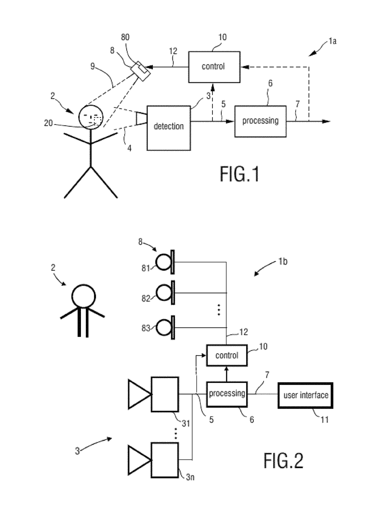
[0041]FIG. 1 shows a device 1a for obtaining vital sign information of a living being 2, e.g. a patient in a hospital, an elderly person monitored in the bed at home, a newborn infants at the NICU or a person doing sports in a fitness club, according to the present invention. The device 1a comprises a detection unit 3 for receiving light 4 in at least one wavelength interval reflected from at least a region of interest of the living being 2 and for generating an input signal 5 from the received light 4. The detection unit 3 is, for instance, configured to register spatio-temporal variations of received light and is preferably an imaging unit for taking images, such as a video camera that substantially continuously or at regular intervals takes images of the living being 2 or at least a region of interest (ROI) 20 of the living being 2.

[0042]The device 1a further comprises a processing unit 6 for processing the input signal 5 and deriving vital sign information 7 of said living being...

second embodiment

[0053]FIG. 2 shows a device 1b for obtaining vital sign information of a living being 2. The device 1b comprises a detection unit 3 including multiple detection elements 31, . . . , 3n, e.g. n cameras. Further, the device 1b comprises an illumination unit 8 including multiple adjustable illumination elements 81, 82, 83, in particular light sources such as LEDs, and a user interface 11. The cameras 31, . . . 3n are used to visually sense the subject(s) being measured under the illumination. The video signal 5 is processed and analysed in the processor 6 to derive the vital sign information 7 (e.g., an SpO2 signal), which can be visualized in the user interface 11, such as a display. The multiple illumination elements 81, 82, 83, are placed at different locations and / or with different angles and are controlled by the control unit 10, based on the camera signal 5 and / or the derived vital sign information 7.

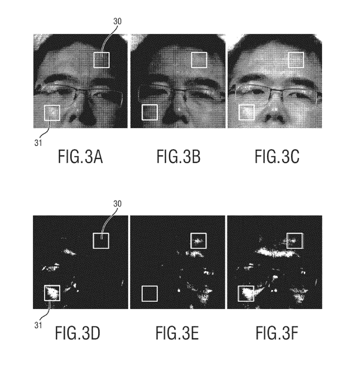
[0054]For camera-based vital sign measurement, one or multiple regions of intere...

third embodiment

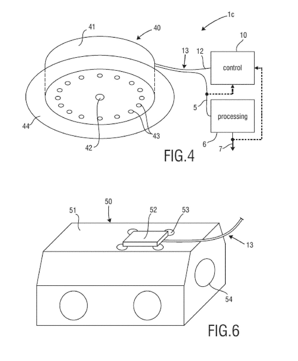
[0070]FIG. 4 shows a schematic diagram of a device 1c for obtaining vital sign information of a living being according to the present invention. In this embodiment an integrated camera frontend 40 including illumination lighting is used, which is connected to the processor 6 and the controller 10 via a cable 13 including signal lines for transmitting the input signals 5 and the control signals 12.

[0071]The integrated camera frontend 40 comprises a frontend housing 41, a camera lens 42 (behind which the camera (not shown) is arranged inside the housing, a plurality of illumination LEDs 43 and a soft suction cup ring for attaching the integrated camera frontend 40 to an incubator or other device.

[0072]In another embodiment a spot light source close to the camera is used to avoid shadows on the image and to keep the location of the field of view of camera and light small. In still another embodiment the light source is made large in area and diffuse in order to minimize the chance to c...


PUM


Abstract

A device for obtaining vital sign information of a living being comprises a detection unit that receives light in at least one wavelength interval reflected from at least a region of interest of a living being and that generates an input signal from the received light. A processing unit processes the input signal and derives vital sign information of the living being from the input signal by use of remote photoplethysmography. An illumination unit illuminates at least the region of interest with light, and a control unit controls the illumination unit based on the input signal and / or the derived vital sign information.

Description

FIELD OF THE INVENTION[0001]The present invention relates to a device and a corresponding method for obtaining vital sign information of a living being.BACKGROUND OF THE INVENTION[0002]Unobtrusive vital sign monitoring using a video camera, or remote PPG (photoplethysmography), has been demonstrated and found relevant for patient monitoring. Remote photoplethysmographic imaging is, for instance, described in Wim Verkruysse, Lars O. Svaasand, and J. Stuart Nelson, “Remote plethysmographic imaging using ambient light”, Optics Express, Vol. 16, No. 26, December 2008. It is based on the principle that temporal variations in blood volume in the skin lead to variations in light absorptions by the skin. Such variations can be registered by a video camera that takes images of a skin area, e.g. the face, while processing calculates the pixel average over a selected region (typically part of the cheek in this system). By looking at periodic variations of this average signal, the heart beat ra...

Claims


Application Information

Patent Timeline
Patent Type & Authority Patents(United States)
IPC IPC(8): A61B5/11A61F7/00A61B5/00A61B5/1455A61B5/024A61G11/00
CPCA61B5/0077A61B5/02427A61B5/02416A61B5/1128A61B5/7278A61F7/007A61G11/00A61B5/14551A61B2505/03A61B2503/045A61B5/00A61B5/0295
Inventor KAESTLE, SIEGFRIED WALTERSHAN, CAIFENG
Owner KONINKLJIJKE PHILIPS NV
Why Eureka
Try Eureka