
Interface circuit and electrical appliance system comprising the same

Active Publication Date: 2017-09-07
ZHONGSHAN BROAD OCEAN
View PDF6 Cites 2 Cited by
  • Summary
  • Abstract
  • Description
  • Claims
  • Application Information

AI Technical Summary

Benefits of technology

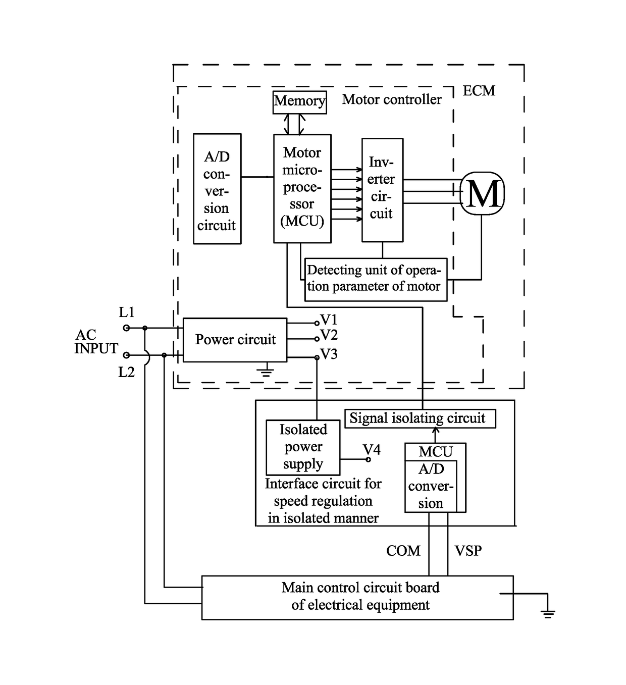
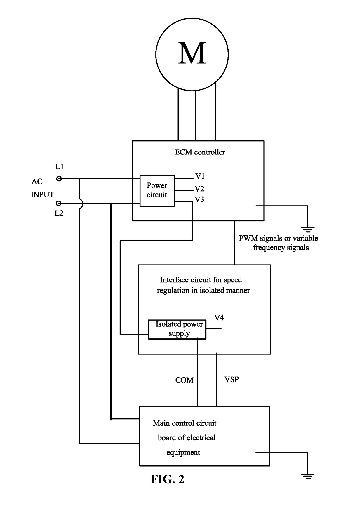
The invention provides an interface circuit for speed regulation in an isolated manner using a low-cost micro control unit (MCU) and an isolated power supply. The MCU is able to read the analog voltage signal and output pulse width modulation (PWM) signals or variable frequency signals, which can then be transmitted to an Electrically Commutated Motor (ECM) through a low-cost signal isolating circuit (digital optocoupler). This design reduces the cost of the interface circuit while ensuring high accuracy and reliability of the signals converted by the MCU. The invention also provides an electrical appliance system comprising this interface circuit for speed regulation, making it simple and cost-effective to control the speed of the ECM.

Problems solved by technology

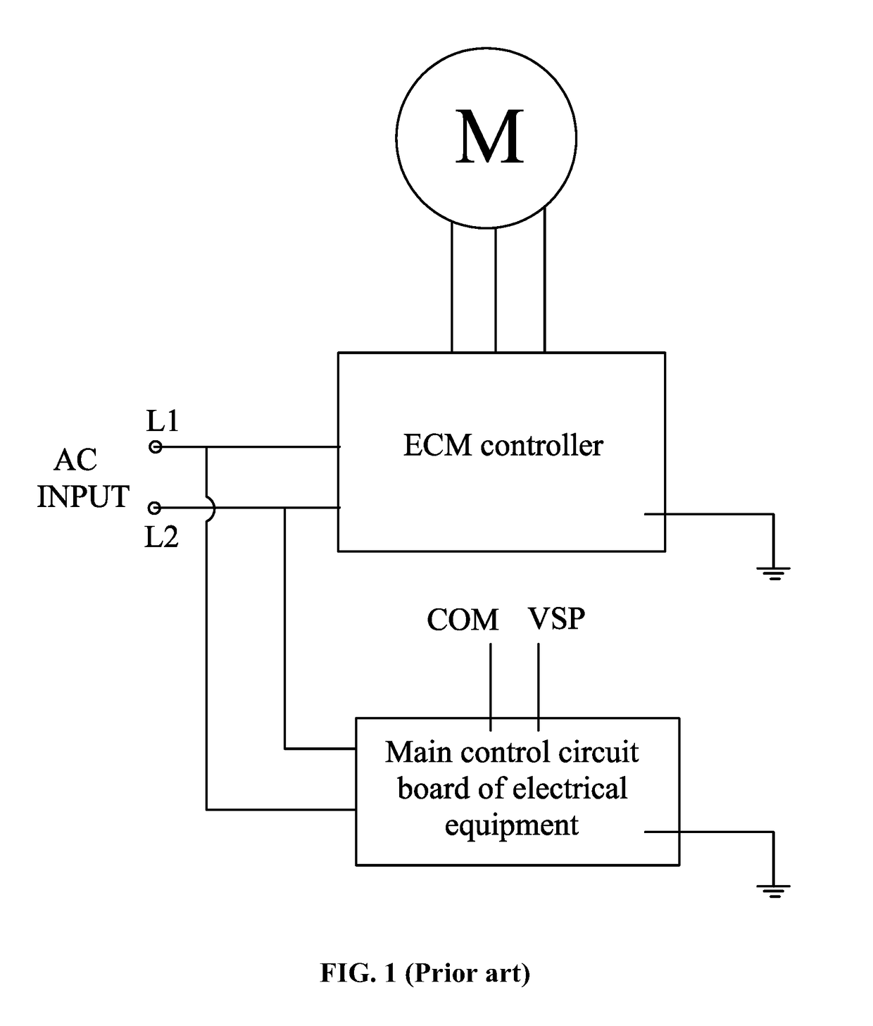
To solve this, signal isolation transmission using linear optocouplers and serial communication using specific communication protocols have been employed, however, both ways are expensive and complex in use.

Method used


Image

  • Interface circuit and electrical appliance system comprising the same
  • Interface circuit and electrical appliance system comprising the same
  • Interface circuit and electrical appliance system comprising the same

Examples


Embodiment Construction

[0034]For further illustrating the invention, experiments detailing an interface circuit for speed regulation in an isolated manner and an electrical appliance system comprising the same are described below.

[0035]As shown in FIGS. 2-3, an electrical appliance system comprises at least one Electronically Commutated Motor (ECM) and a main control circuit board of electrical equipment. The ECM and the main control circuit board are connected to an AC input power supply. The ECM and the main control circuit board are connected to independent grounding wires. The main control circuit board is configured to output between 0 and 10 V analog voltage signals to control speed of the ECM. The ECM is connected to the main control circuit board via an interface circuit for speed regulation in an isolated manner. The interface circuit for speed regulation in an isolated manner comprises a MCU, an isolated power supply, and a signal isolating circuit. The MCU, the isolated power supply, and the si...


PUM


Abstract

An interface circuit, including: a micro control unit (MCU), an isolated power supply, and a signal isolating circuit. The MCU, the isolated power supply, and the signal isolating circuit are integrated on a circuit board. The output end of the isolated power supply supplies power for circuits. The input end of the isolated power supply is connected to an external input power supply. The A / D conversion input port of the MCU is connected to the analog voltage signals. The MCU is configured to convert the analog voltage signals into pulse width modulation (PWM) signals or variable frequency signals with certain duty cycles, and output the PWM signals or the variable frequency signals to the input end of the signal isolating circuit. The signal isolating circuit is configured to output the PWM signals or the variable frequency signals with certain duty cycles.

Description

CROSS-REFERENCE TO RELATED APPLICATIONS[0001]This application is a continuation-in-part of International Patent Application No. PCT / CN2015 / 077457 with an international filing date of Apr. 24, 2015, designating the United States, now pending, and further claims foreign priority benefits to Chinese Patent Application No. 201410818673.8 filed Dec. 24, 2014. The contents of all of the aforementioned applications, including any intervening amendments thereto, are incorporated herein by reference. Inquiries from the public to applicants or assignees concerning this document or the related applications should be directed to: Matthias Scholl P. C., Attn.: Dr. Matthias Scholl Esq., 245 First Street, 18th Floor, and Cambridge, Mass. 02142.BACKGROUND OF THE INVENTION[0002]Field of the Invention[0003]The invention relates to an interface circuit for speed regulation in an isolated manner and an electrical appliance system comprising the same.[0004]Description of the Related Art[0005]Electrical ...

Claims


Application Information

Patent Timeline
IPC IPC(8): H02P7/06H02P6/16H02P6/06H03K7/08H02P6/12H02P7/29H02P6/26
CPCH02P7/06H02P7/29H02P6/16H02P6/06H03K7/08H02P6/12H02P6/26H02P27/08
Inventor BIAN, WENQING
Owner ZHONGSHAN BROAD OCEAN
Learn More