
Method and apparatus for determining the skin temperatures of heat-exchange tubes in a fired tubular gas heater

a technology of heat exchange tubes and gas heaters, which is applied in the direction of instruments, heat measurement, thermometer details, etc., can solve the problems of inability to accurately measure the actual temperature of the instrument, presenting a high degree of inaccuracy, and no prior art method or device provides reliable measurement of such temperature. achieve the effect of high accuracy and reliability

Inactive Publication Date: 2017-01-05
HYL TECH SA DE CV +2
View PDF0 Cites 1 Cited by
  • Summary
  • Abstract
  • Description
  • Claims
  • Application Information

AI Technical Summary

Benefits of technology

The patent is about a method and device that can accurately determine the temperature of heat-exchange tubes in a gas heater to improve safety and prevent damage to the tubes. This technology helps prevent overheating and reduces the need for expensive repairs and plant shutdowns.

Problems solved by technology

The applicants have found the following patents and technical publications related to determination of the tube wall temperatures, however none of the prior art methods or devices provide a reliable measurement of such temperature, mainly due to the extreme conditions in the heater radiation zone for installing thermocouples in the tubes.
The method needs measurement of the skin temperature of the tubes, which presents a high degree of inaccuracy.
If a pyrometer is used, the hot gases of the flames inside the furnace cause that the reading of the instrument may be way off the actual temperature.
This method is not reliable to be used as an on-line tool for a furnace operation because it is based on a set of relationships of the process variables of the plant which do not take into account actual changes in the operation.
Barkley describes some of the problems related to the use of thermocouples for monitoring said tube skin temperature.
The teachings of this patent however are not directly applicable to the type of gas heaters used in the direct reduction plants or the petrochemical industry because the range of operating temperatures of the steam re-heaters in boilers are considerably lower than the operating temperatures of the heaters used in direct reduction plants.

Method used


Image

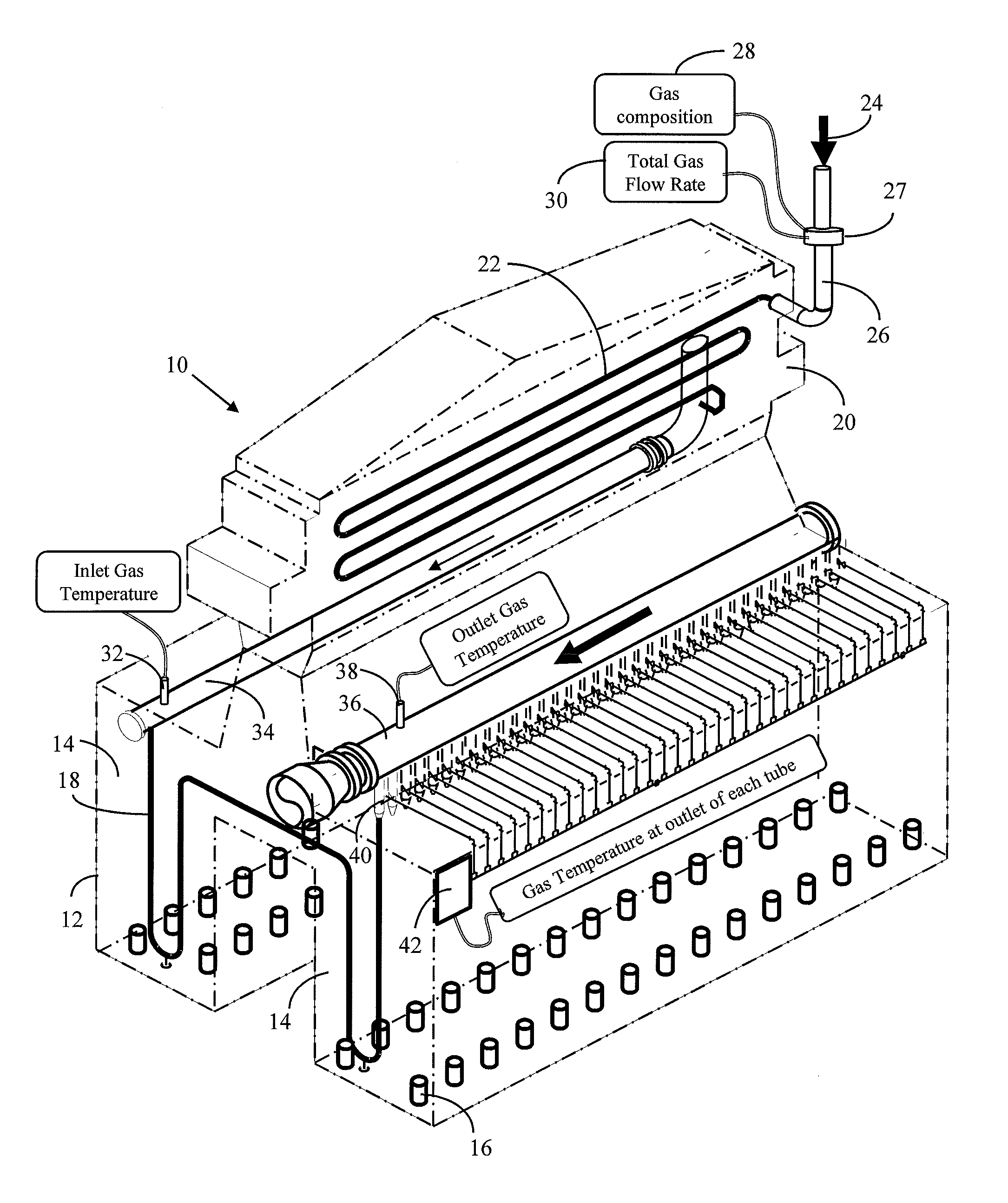
  • Method and apparatus for determining the skin temperatures of heat-exchange tubes in a fired tubular gas heater
  • Method and apparatus for determining the skin temperatures of heat-exchange tubes in a fired tubular gas heater
  • Method and apparatus for determining the skin temperatures of heat-exchange tubes in a fired tubular gas heater

Examples


example

[0060]The operational parameters provided for calculating Q the overall heat transferred through the tubes were:[0061]F=52,000 NCMH=Total gas flow rate as measured in-line[0062]T1=500° C.=gas temperature at inlet of radiant zone[0063]T2=950° C.=gas temperature at outlet of radiant zone

With the above data from measurements in the heater and the specific values of the dimensions of the tubes and the composition of the gas, using equation 2 the overall heat transferred through the tubes was calculated as 159,887 BTU / hr.

[0064]After calculation of the total transferred heat Q, the value of Q was used in Equation 1 to calculate Ts the tube skin temperature of the selected tube (having the highest gas temperature).

[0065]The following values of the variables in equation 1 were used:[0066]L=ft=Total length of tubes[0067]Tg=980° C.=Highest temperature of the gas at outlet of the tube selected from the values of temperature obtained from the monitoring cycle of all the heat-exchange tubes.[006...


PUM


Abstract

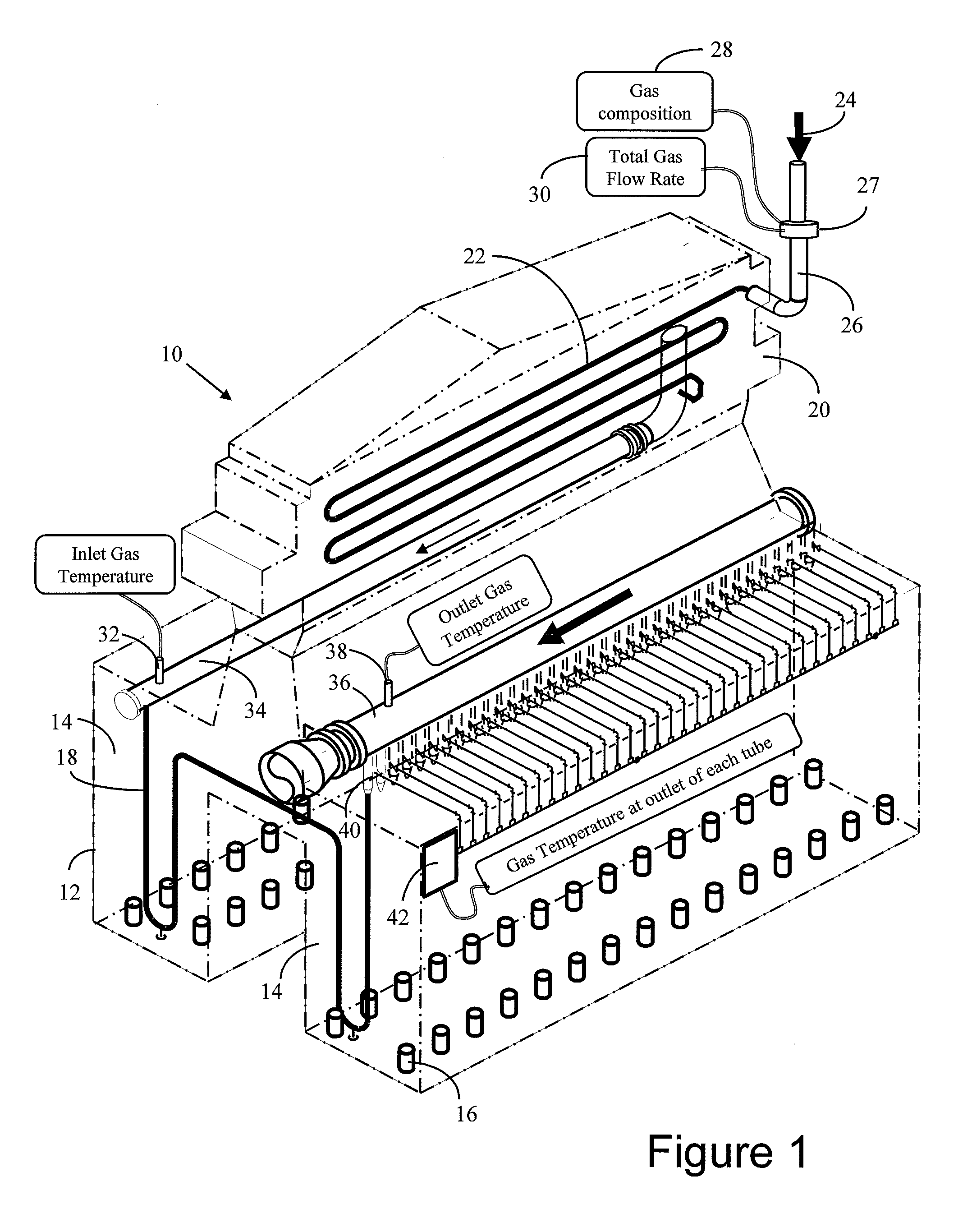
Method and apparatus to determine the skin-temperature of heat-exchange tubes and to prevent overheating of the heat-exchange tubes in a process gas heater (where extreme conditions prevent obtaining sufficiently-accurate direct thermocouple or pyrometric measurement to reliably prevent such overheating) by calculating the maximum skin temperature of heat-exchange tubes using preferably real-time calculation of the overall heat flux through the walls of the heat-exchange tubes with preferably real-time values of gas composition and gas temperature at the inlet and at the outlet of the tubes to calculate the overall transferred heat; and by periodically measuring the temperature of the gas flowing through each of the heat-exchange tubes, and using the measured gas temperatures for calculating the skin-temperature of all tubes, or of a tube selected for the highest gas temperature using the equation:Q=2πL(Ts-Tg) / (lnroriKm).The highest value of skin-temperature can be used to take corrective actions to avoid tubes overheating.

Description

FIELD OF THE INVENTION[0001]The invention relates to the field of industrial plants where a gas stream is heated in a tubular heater by heat exchange through the walls of heat-exchange tubes and wherein the process gas being heated passes through said tubes receiving heat from the combustion of a fuel outside of said heating tubes.BACKGROUND OF THE INVENTION[0002]Fuel fired tubular process-gas heaters are used in a number of industrial processes to raise the temperature of a fluid (such as a process gas, which after heating is processed or used in other parts of the plant. Examples of this type of industrial processes are petrochemical reforming processes (such as in U.S. Pat. No. 4,400,784) and direct reduced iron (DRI) plants (such as in U.S. Pat. Nos. 4,528,030; 5,858,057).[0003]In order to heat a gas to high temperatures, for example above 800° C. and preferably above 900° C. in a DRI production plant, the gas is heated in a direct fired tubular heater having a series of heat-ex...

Claims


Application Information

Patent Timeline
IPC IPC(8): G01K13/00
CPCG01K1/143G01K7/42
Inventor BECERRA-NOVOA, JORGE-OCTAVIOGUERRA-REYES, MARIA-TERESARAMJEWAN, ANTHONYMARTINIS, ALESSANDRO
Owner HYL TECH SA DE CV
Learn More