Engine intake manifold assembly

a technology of intake manifold and assembly, which is applied in the direction of air intake for fuel, combustion-air/fuel-air treatment, machines/engines, etc., can solve the problems of limiting the design flexibility of components, laborious, and high cost of shapes and forms

Inactive Publication Date: 2005-01-13
DOW GLOBAL TECH LLC
View PDF99 Cites 45 Cited by
  • Summary
  • Abstract
  • Description
  • Claims
  • Application Information

AI Technical Summary

Benefits of technology

[0008] The present invention illustrates such improvements particularly in the area of assembling intricately shaped intake manifold assemblies from components of the same materials, or more preferably from components having dissimilar materials. Thus, in one preferred aspect the present invention contemplates a method for making an intake manifold for an automotive vehicle, comprising ...

Problems solved by technology

This tends to require many parts and therefore is labor intensive.
While these tend to result in desirable near net shape products, the shapes of which may be complex, they typically are expensive.
Such joining, however...

Method used


Image

  • Engine intake manifold assembly
  • Engine intake manifold assembly
  • Engine intake manifold assembly

Examples


Embodiment Construction

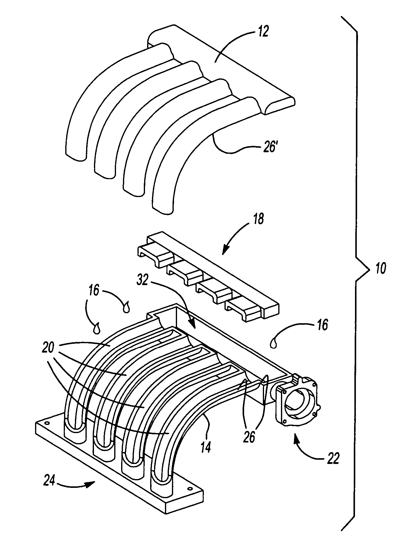
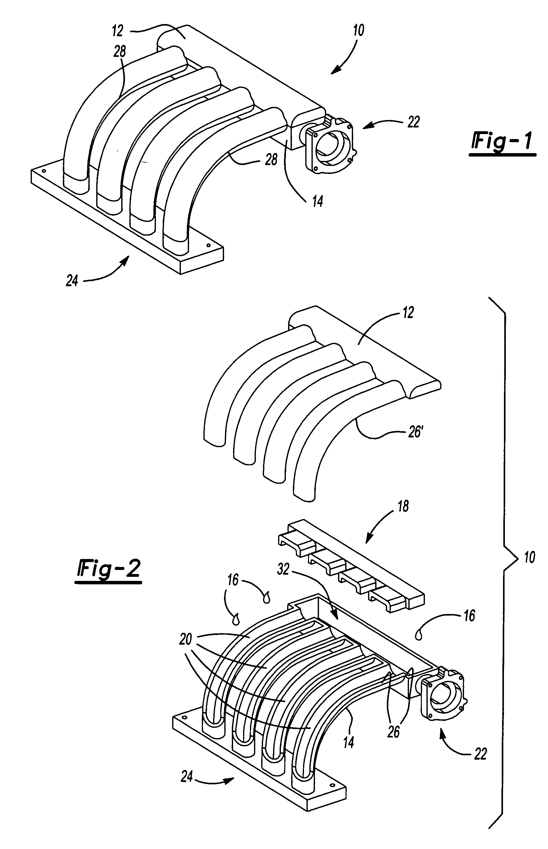
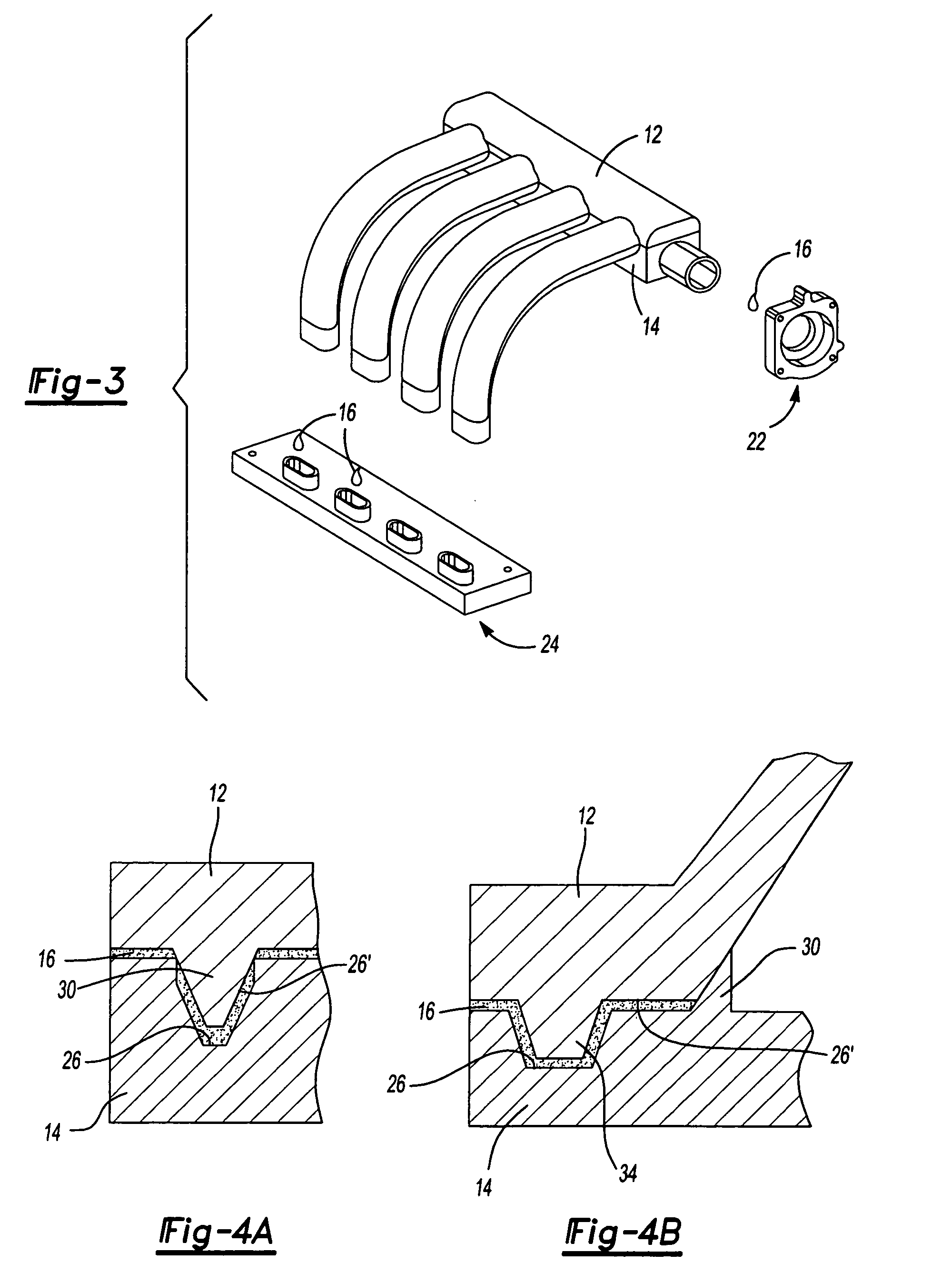
[0017] Referring to FIGS. 1-3, there is shown an intake manifold assembly 10 of the present invention including a first portion 12 and a second portion 14. The first portion 12 and the second portion 14 are joined together, preferably with an intermediate adhesive 16 to form the intake manifold. In a preferred embodiment the joining of the first and second manifold portion forms one or more runners for defining an airflow space.

[0018] Either or both of the first or second portions can include one or more additional coatings, layers or components (e.g., a primer, a plasma coating or other surface treatment). Other surface treatments such as sanding, scuffing, corona treatment, laser treatment, flame treatment, combinations thereof or the like may be performed upon the portions. Optionally, either or both of the first portion 12 or second portion 14 has structure for facilitating joinder or location of the portions relative to each other, to an engine head, or to another engine compo...


PUM

PropertyMeasurementUnit
Flow rateaaaaaaaaaa
Diameteraaaaaaaaaa
Adhesivityaaaaaaaaaa

Abstract

An engine intake manifold assembly including a first portion configured with a first material and a second portion configured with a second material, wherein the first and second portions are adhesively bonded together. Preferably, the intake manifold assembly is additionally configured with a cylinder head flange, for mounting the same to an automotive engine component, and a throttle body attachment for attachment of a throttle body component. The cylinder head flange and throttle body attachment may be an integral component of the first or second portions or attached to the same during or after assembly of the first and second portions. Optionally, an insert is located between the assembled first and second portion to create one or more plenums thereby creating one or more air flow paths through the intake manifold assembly.

Description

CLAIM OF BENEFIT OF FILING DATE [0001] The present application claims the benefit of the filing date of U.S. Provisional Application Ser. No. 60 / 486,038, filed Jul. 10, 2003, hereby incorporated by reference.TECHNICAL FIELD [0002] The present invention relates to adhesively bonded engine component assemblies and more particularly to adhesively bonded intake manifold assemblies. BACKGROUND OF THE INVENTION [0003] Historically, fabrication techniques have involved the fabrication of separate metal components and joining the components using fasteners, with an intermediate disposed gasket. This tends to require many parts and therefore is labor intensive. [0004] Plastic engine intake manifold assemblies (such as for automotive vehicle engines) have been fabricated by near net shape manufacturing processes, such as lost core processes. While these tend to result in desirable near net shape products, the shapes of which may be complex, they typically are expensive. [0005] In another popu...

Claims


Application Information

Patent Timeline
IPC IPC(8): F02M35/10F02M35/104
CPCB29C65/1406Y10T29/49231B29C65/4835B29C65/484B29C65/4845B29C65/485B29C65/7829B29C66/124B29C66/131B29C66/54F02M35/10144F02M35/10216F02M35/10268F02M35/10321F02M35/10327F02M35/10347F02M35/1036F02M35/112B29C65/4865B29C65/48B29C65/4815B29C65/483B29C65/1412F02M35/10F02M35/104
Inventor ASFAW, SELAMAWITCEDERSTROM, JAMESBREWSTER, CHRISTOPHER ANTHONYKRAJEWSKI, BRIAN ANTHONY
Owner DOW GLOBAL TECH LLC
Why Eureka
Try Eureka