Ergonomic cable tie installation tool

a cable tie and installation tool technology, applied in the direction of wire tools, manufacturing tools, bundling machine details, etc., can solve the problem of more linear displacement of the trigger linkage relative to the grip, and achieve the effect of increasing the tension of the cable ti

Active Publication Date: 2005-01-13
THOMAS & BETTS INT INC
View PDF35 Cites 29 Cited by
  • Summary
  • Abstract
  • Description
  • Claims
  • Application Information

AI Technical Summary

Benefits of technology

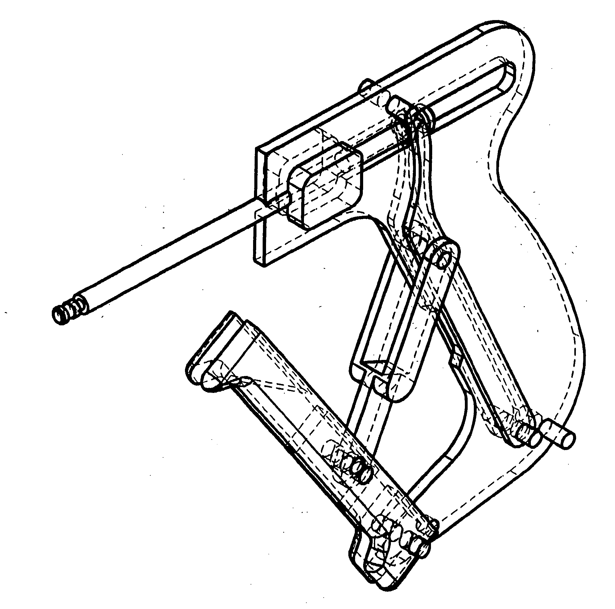
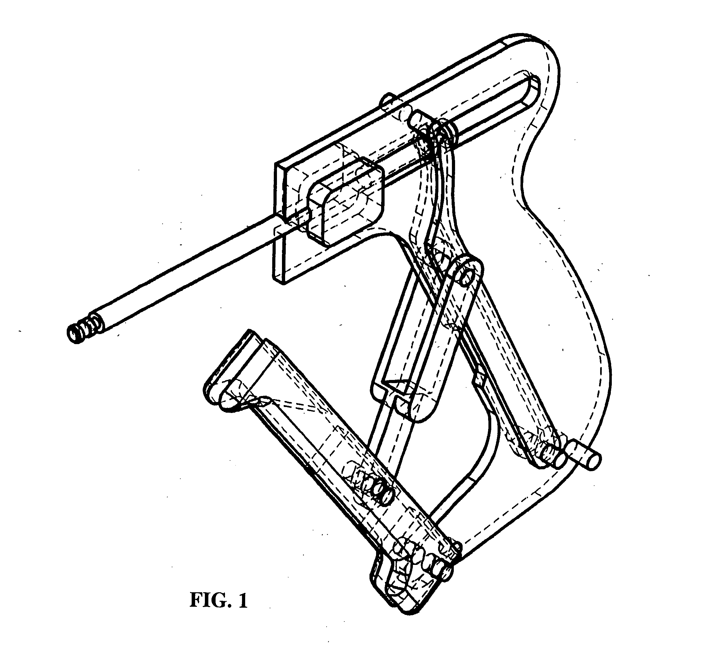
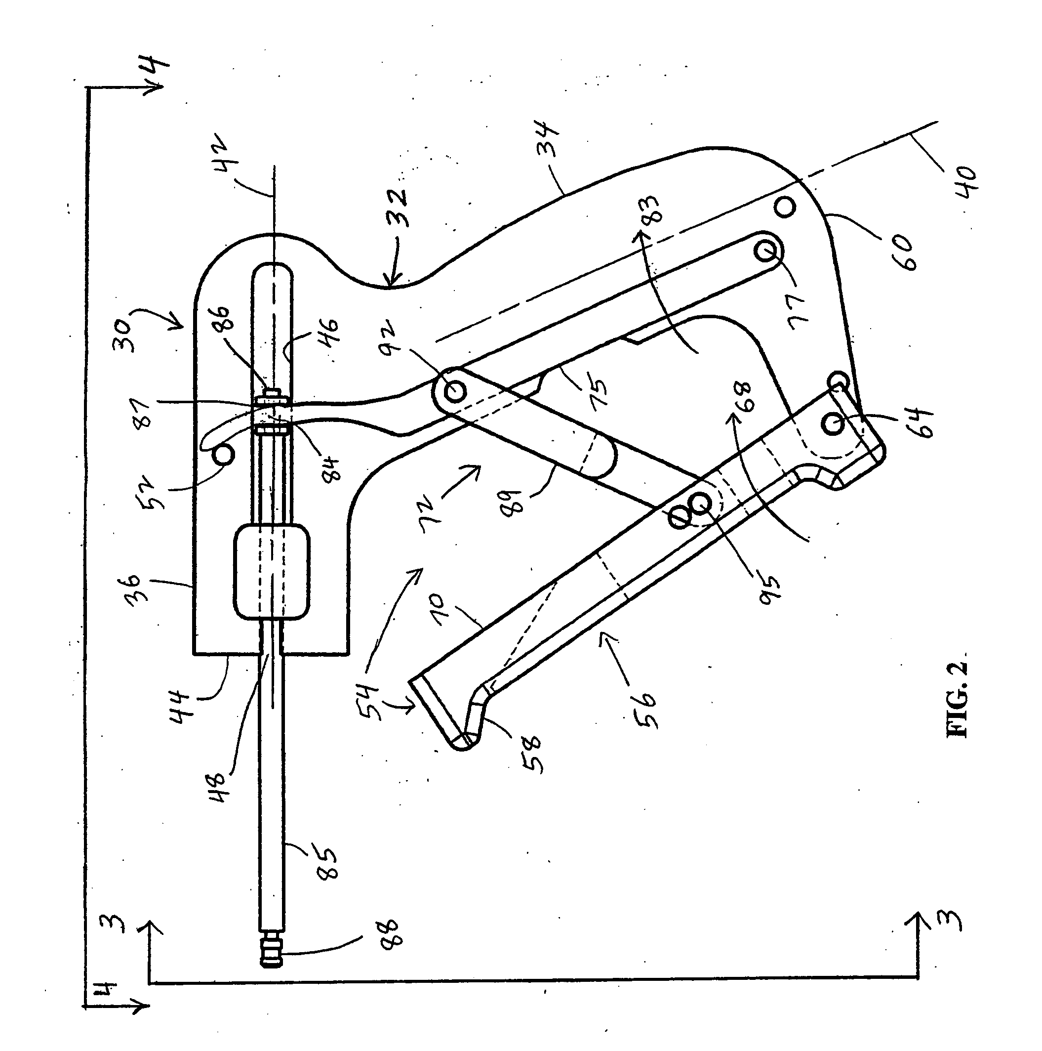
[0007] The ergonomic cable tie installation tool of the present invention includes a generally pistol-shaped housing including a grip which depends from a barrel. Pivotally connected to the lower region of the grip is a trigger linkage of a trigger mechanism. The trigger mechanism also includes an intermediate linkage to which the trigger linkage is connected. The intermediate linkage is supported in the housing. The intermediate linkage is, in turn, connected to a tensioning mechanism also supported in the housing. The tensioning mechanism couples the intermediate linkage to the cable tie. Pivoting the trigger linkage toward the grip, normally by the hand of a user, causes the intermediate linkage to pivot resulting in the tensioning mechanism producing an increased tension in the cable tie. The trigger linkage is oriented relative to the grip to provide several ergonomic advantages to the user's hand when grasping the trigger linkage and grip.

Problems solved by technology

Also, such a trigger mechanism may reduce the inclination of the trigger linkage relative to the grip so that squeezing of the trigger linkage results in more linear displacement of the trigger linkage relative to the grip.

Method used


Image

  • Ergonomic cable tie installation tool
  • Ergonomic cable tie installation tool
  • Ergonomic cable tie installation tool

Examples


second embodiment

[0062] An alternative second embodiment of the cable tie installation tool 30a is shown in FIGS. 7 to11. FIGS. 7 to 11 are views which correspond to the views of FIGS. 1 to 4, and 6, respectively. Parts illustrated in FIGS. 7 to 11 which correspond to parts illustrated in FIGS. 1 to 4, and 6 have, in FIGS. 7 to 11, the same reference numeral as in FIGS. 1 to 4, and 6 with the addition of the suffix “a”.

[0063] The tool 30a includes an elongate outer trigger member 97. Accordingly, the trigger member 58a is referred to as the inner trigger member 58a of the tool 30a. The outer trigger member 97 has a dual-member structure, as shown in FIG. 7.

[0064] The respective members of the trigger member 97 each have one end which is pivotally connected to an end of the respective members of the inner trigger member 58a which are opposite from the pivotal connections 64a. Each of the members of the trigger member 97 has a longitudinal axis 98 which is generally parallel to the central plane 38a,...

third embodiment

[0080] An alternative third embodiment of the cable tie installation tool 30c, which is a preferred embodiment of the present invention, is shown in FIGS. 12 to 23. FIGS. 21 to 23 are views which correspond generally to the views of FIGS. 1, 2 and 6, and FIGS. 7, 8 and 11, respectively. Parts illustrated in FIGS. 21 to 23 which correspond to parts illustrated in FIGS. 1, 2 and 6, and FIGS. 7, 8 and 11 have, in FIGS. 21 to 23, the same reference numeral as in FIGS. 1, 2 and 6, and FIGS. 7, 8 and 11 with the addition of the suffix “b”. The suffix “a”, included in some of the reference numerals of FIGS. 7, 8 and 11, is not included in FIGS. 21 to 23, since the correspondence to such parts in FIGS. 7, 8 and 11 is sufficiently indicated by the corresponding numbers.

[0081] FIGS. 12 to 21 show the housing frame 32b, and additionally show the outer shell of the housing which is designated generally by the reference numeral 119. The outer shell 119 includes a shell 120 in which the housing f...

fourth embodiment

[0093] An alternative fourth embodiment of the tool 30c, which is a preferred embodiment of the present invention, is shown in FIGS. 25 to 27. FIGS. 25 to 27 are views which correspond generally to the views of FIGS. 1 to 3, FIGS. 7 to 9, and FIGS. 22, 23 and 20, respectively. Parts illustrated in FIGS. 25 to 27 which correspond to parts illustrated in FIGS. 1 to 3, FIGS. 7 to 9, and FIGS. 22, 23 and 20 have, in FIGS. 25 to 27, the same reference numeral as in FIGS. 1 to 3, FIGS. 7 to 9, and FIGS. 22, 23 and 20 with the addition of the suffix “c”. The suffixes “a” and “b”, included in some of the reference numerals of FIGS. 7 to 9, and FIGS. 22, 23 and 20, are not included in FIGS. 25 to 27, since the correspondence to such parts in FIGS. 7 to 9, and FIGS. 22, 23 and 20 is sufficiently indicated by the corresponding numbers.

[0094] As shown in FIG. 25, the tool 30c has particular correspondence to the tool 30b shown in FIG. 22. The tool 30c includes a return spring designated general...


PUM

PropertyMeasurementUnit
tensionaaaaaaaaaa
distanceaaaaaaaaaa
axis of rotationaaaaaaaaaa

Abstract

An ergonomic cable tie installation tool includes a generally pistol-shaped housing including a grip which depends from a barrel. Pivotally connected to the lower region of the grip is a trigger linkage of a trigger mechanism. The trigger mechanism also includes an intermediate linkage pivotally connected to the trigger linkage. The intermediate linkage is supported in the housing. The intermediate linkage is, in turn, connected to a tensioning mechanism also supported in the housing. The tensioning mechanism couples the intermediate linkage to the cable tie. Pivoting the trigger linkage toward the grip, normally by the hand of a user, causes the intermediate linkage to pivot resulting in the tensioning mechanism producing an increased tension in the cable tie. The trigger linkage is oriented relative to the grip such that pivoting it toward the grip requires the stronger fingers of the user's hand to travel more than the weaker fingers thereby improving the ergonomics of the tool. The trigger linkage may also make the respective travel distances of the stronger and weaker fingers more uniform also improving the ergonomics of the cable tie installation tool. Moreover, the trigger mechanism may provide for the tension force applied to the cable tie to increase as the trigger linkage is increasingly pivoted toward the closed position. Methods of operating the tool also provide improved ergonomics of the tool.

Description

BACKGROUND OF THE INVENTION [0001] The present invention relates generally to a cable tie installation tool, and more specifically, to such a tool having an ergonomic trigger mechanism. [0002] As is well known to those skilled in the art, cable ties (or straps) are used to bundle or secure a group of articles such as electrical wires or cables. Cable ties of conventional construction include a cable tie head and an elongate tail extending therefrom. The tail is wrapped around a bundle of articles and thereafter inserted through a passage in the head. The head of the cable tie typically supports a locking element which extends into the head passage allowing the tail to be inserted through the passage but preventing retraction of the tail through the passage in the head. Two longitudinally separated portions of the tail are thereby secured to the head to define a loop for holding together the group of articles. [0003] In practice, the installer manually places the tie about the articl...

Claims


Application Information

Patent Timeline
Patent Type & Authority Applications(United States)
IPC IPC(8): B21F9/02B65B13/02B65B13/22H02G1/06
CPCB65B13/22B65B13/027
Inventor MAGNO, JOEY D. JR.POPE, BRIAN A.
Owner THOMAS & BETTS INT INC
Why Eureka
Try Eureka